
Image processing apparatus and method of same

a technology of image processing and drawing device, which is applied in the direction of processing device architecture/configuration, instruments, computing, etc., can solve the problems of complex processing, drop in the performance of drawing device, and processing constraints, so as to improve the performance of graphics drawing processing of drawing device, efficiently draw images, and reduce the number of minute units of graphics

Inactive Publication Date: 2008-05-13
SONY CORP
View PDF17 Cites 0 Cited by
  • Summary
  • Abstract
  • Description
  • Claims
  • Application Information

AI Technical Summary

Benefits of technology

[0013]An object of the present invention is to provide an image processing apparatus able to decrease the number of minute unit graphics, able to achieve an improvement of performance of the graphics drawing processing of a drawing device, and able to efficiently draw images, and a method of the same.

Problems solved by technology

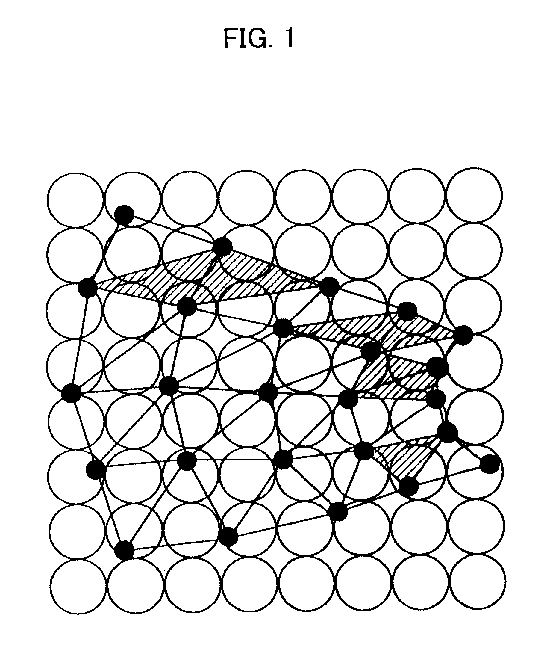
Such a so-called 0 pixel triangle (triangle not including the center of a pixel) causes a drop in the performance of a drawing device.
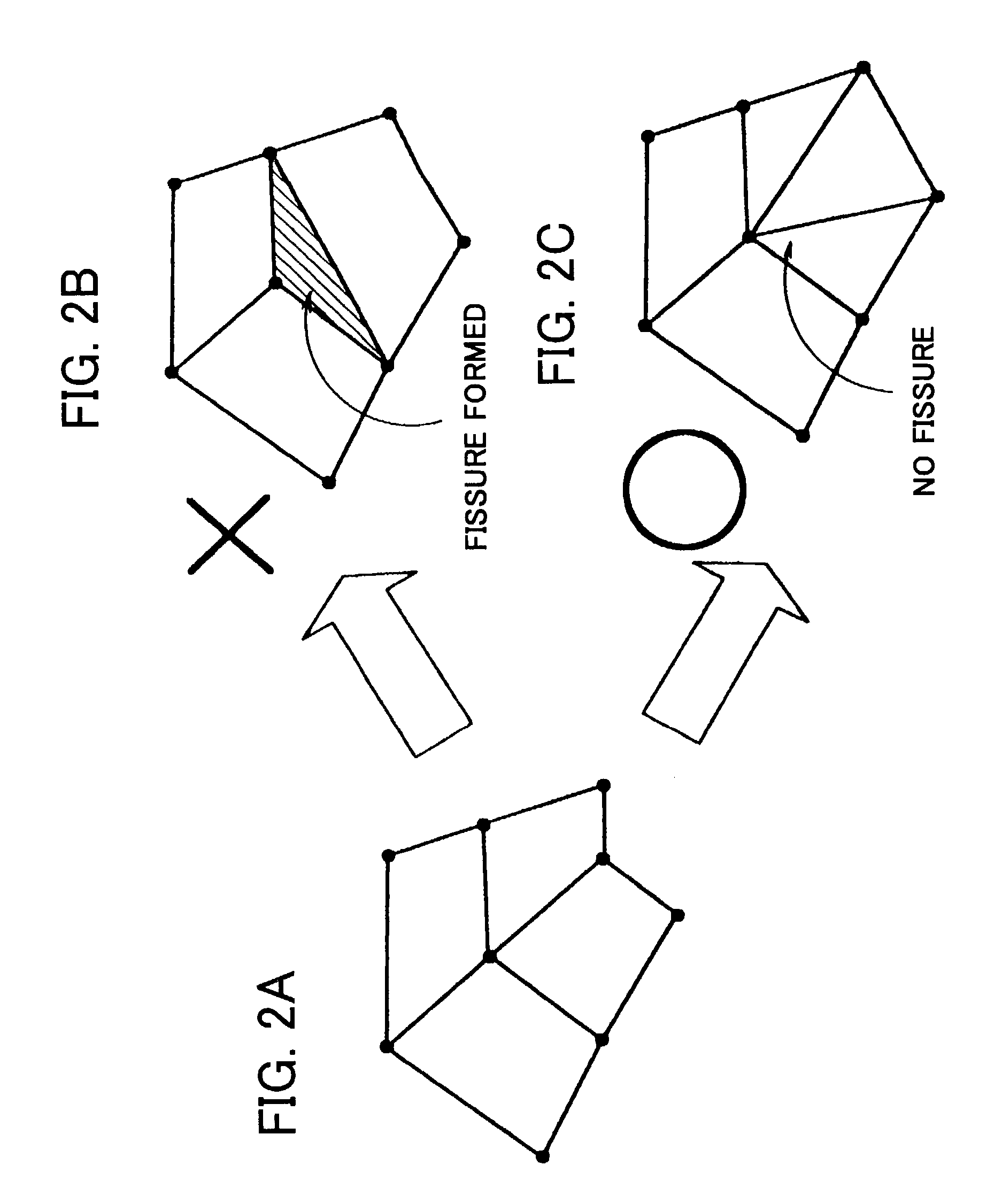
Accordingly, in a conventional image processing apparatus, where adaptively generating triangles without using a regular pattern, as shown in FIG. 2C, it is necessary to take care not to generate a fissure, so there are the disadvantages that there are constraints on the processing and complex processing is required.

Method used


Image

  • Image processing apparatus and method of same
  • Image processing apparatus and method of same
  • Image processing apparatus and method of same

Examples


first embodiment

[0053]FIG. 3 is a view of the system configuration of a first embodiment of a three-dimensional computer graphics system 10 as an image processing apparatus according to the present invention.

[0054]The three-dimensional computer graphics system 10 is a system for polygon rendering for expressing a cubic model (primitive) as a combination of unit graphics, that is, triangles (polygons or triangles), determining the color of each pixel of the display screen by drawing these polygons, and displaying the same on a display. Further, the three-dimensional computer graphics system 10 expresses the three-dimensional object by using a z-coordinate for expressing the depth in addition to (x, y) coordinates for expressing a position on a plane and specifies any point in a three-dimensional space by these three coordinates (x, y, z).

[0055]As shown in FIG. 3, the three-dimensional computer graphics system 10 has a main processor (CPU) 11, a main memory 12, a graphics processor 13, and a monitor ...

second embodiment

[0132]FIG. 21 is a view of the system configuration of a second embodiment of a three-dimensional computer graphics system 10 as an image processing apparatus according to the present invention.

[0133]The difference of the second embodiment from the first embodiment resides in the processing of the graphics processor 13A.

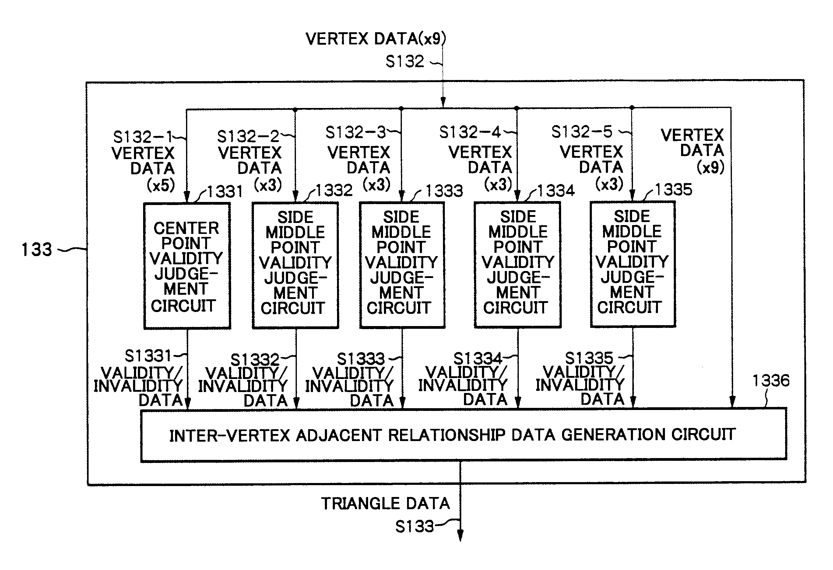
[0134]Namely, the first embodiment processed the vertex data in the geometry processor 132 by coordinate conversion, clipping, lighting, and other geometry processing processing, generated vertex data S132 of nine points converted from the world coordinate system to the screen coordinate system, and judged the validity / invalidity of each vertex at the triangle generator 133.

[0135]As opposed to this, the second embodiment arranges a screen coordinate calculation device 137 after the vertex generator 131, calculates only the xy coordinates in the screen coordinate system required for the judgment of validity / invalidity of the vertexes, inputs the vertex data S137 after...


PUM


Abstract

An image processing apparatus able to decrease the number of minute unit graphics, able to achieve an improvement of performance of graphics drawing processing, and able to efficiently generate images, provided with a triangle generator for receiving vertex data from a geometry processor, selecting a plurality of vertexes other than predetermined end points from among 3×3 vertexes forming a mesh, judging whether each selected vertex is valid or invalid based on a distance between the selected vertex and an adjacent vertex, generating triangle data based on validity / invalidity information of each vertex, and outputting the same via a triangle buffer to a triangle drawing device.

Description

BACKGROUND OF THE INVENTION[0001]1. Field of the Invention[0002]The present invention relates to an image processing apparatus for expressing a model by a combination of unit graphics and a method of the same.[0003]2. Description of the Related Art[0004]Along with the improvement in operating speeds and strengthening of graphics generation functions in recent computer systems, computer graphics (CG) technology for preparing and processing graphics and images using computer resources is being actively researched and developed and being put into practical use.[0005]For example, in three-dimensional graphics, the optical phenomenon when a three-dimensional object is illuminated by a predetermined light source is expressed by a mathematical model and the surface of the object is given shading or brightness or further given a texture based on this model so as to generate a more realistic, three-dimensional-like two-dimensional high definition image. Such computer graphics is now being in...

Claims


Application Information

Patent Timeline
IPC IPC(8): G06T15/00G06T1/20G06T17/00G06T17/20
CPCG06T17/20
Inventor INADA, TETSUGO
Owner SONY CORP
Learn More