
Apparatus and method for holding garments

a technology for garments and accessories, applied in the direction of retainers, neckties, press-button fasteners, etc., can solve the problems of damage to clothing, inability to securely fasten multiple layers of clothing together, and inability to permit easy separation of the ornamental end of the necktie from the shir

Inactive Publication Date: 2008-05-20
SCHOENING BRIAN +3
View PDF22 Cites 83 Cited by
  • Summary
  • Abstract
  • Description
  • Claims
  • Application Information

AI Technical Summary

Problems solved by technology

But permanent magnets made of traditional materials have not been capable of securely fastening multiple layers of clothing together due to their relatively weak magnetic field strengths.
However, conventional necktie holders such as these suffer from several shortcomings; namely, they may not be completely hidden from view, they may not have interchangeable decorative faceplates, they may not fixedly attach the necktie against the surface of the shirt, they may damage clothing by leaving a hole through the necktie and / or the shirt, and they may not permit easy separation of the ornamental end of the necktie from the shirt while simultaneously retaining the necktie holder.
In addition, conventional necktie holders can be dangerous for those persons who are required to wear a break-away necktie (i.e. clip-on tie) in their professions because conventional necktie holders are incapable of allowing the necktie to smoothly separate from the wearer's neck if the necktie were to become caught in machinery, for example.
However, Baker neither teaches nor suggests that all of the components of the necktie holder are completely hidden from view.
However, Lee neither teaches nor suggests a necktie holder capable of fixedly attaching the necktie to be in direct contact with the surface of the shirt.

Method used


Image

  • Apparatus and method for holding garments
  • Apparatus and method for holding garments
  • Apparatus and method for holding garments

Examples


Embodiment Construction

[0034]While this invention is susceptible of embodiment in many different forms, there are shown in the drawings and described in detail, certain preferred embodiments with the understanding that the present disclosure should be considered as an exemplification of the principles of the invention and is not intended to limit the invention to the embodiments so illustrated.

[0035]FIGS. 1-3 describe a generic magnet and faceplate combination as used in the present invention. Magnet 10 is preferably made from a rare Earth material 11, such as Neodymium Iron Boron (NdFeB), sintered to form a permanent magnet of about Grade N35 (i.e. preferably a magnet having BHmax equal to about 33 to 35 Million Gauss Oersted energy units (MGOe), where BHmax is the maximum product of the induction (B) measured in Gauss units and the magnetic field strength (H) measured in Oersted units). Magnet 10 is encased by coating 14 to prevent corrosion of the underlying rare Earth substrate. Besides protecting rar...

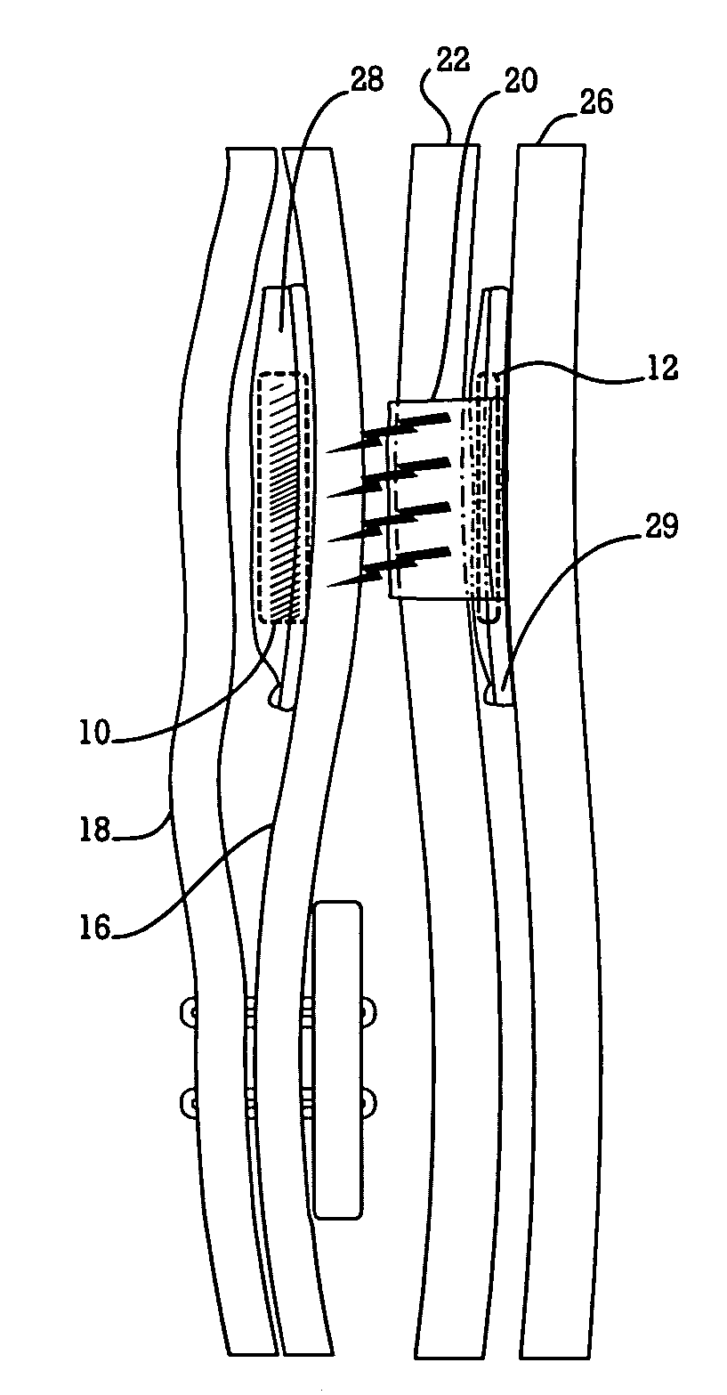
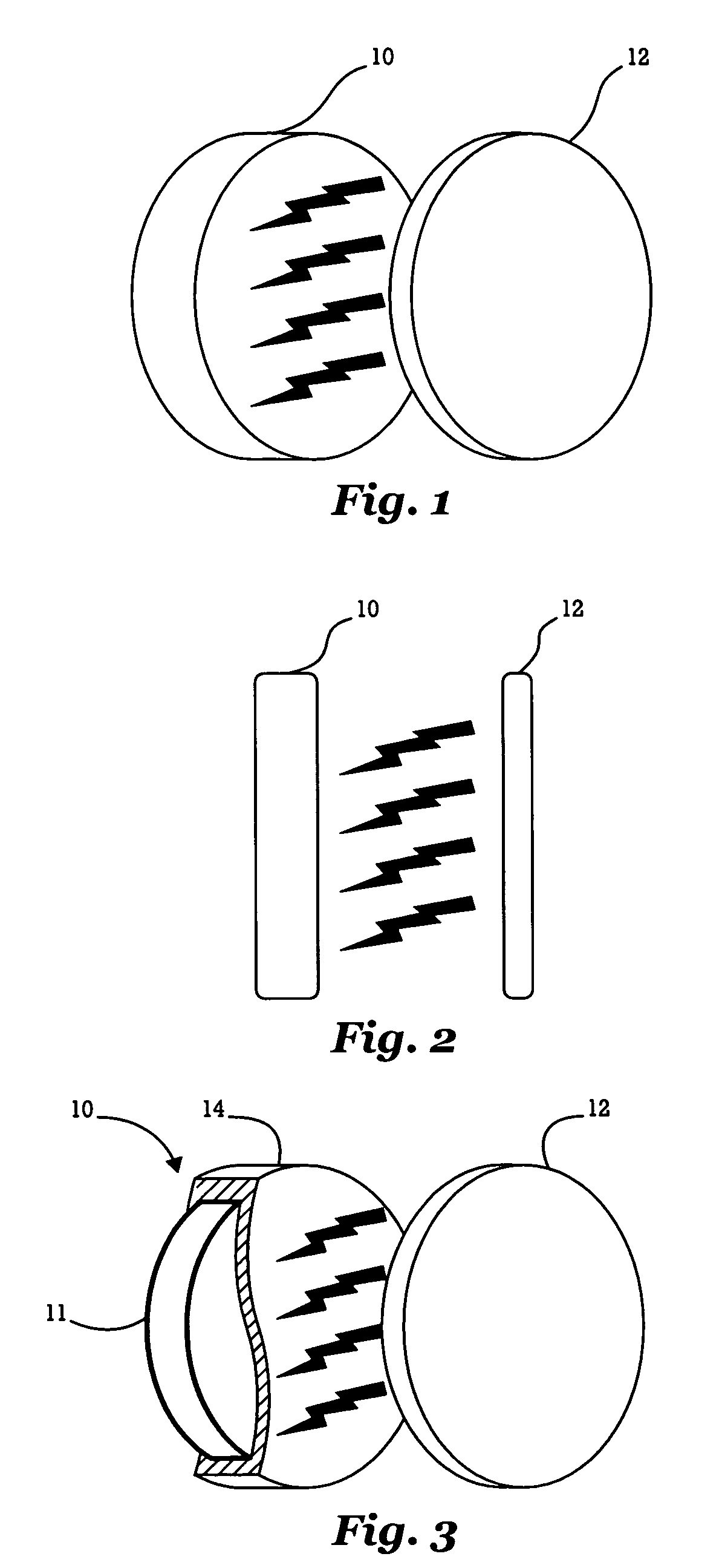
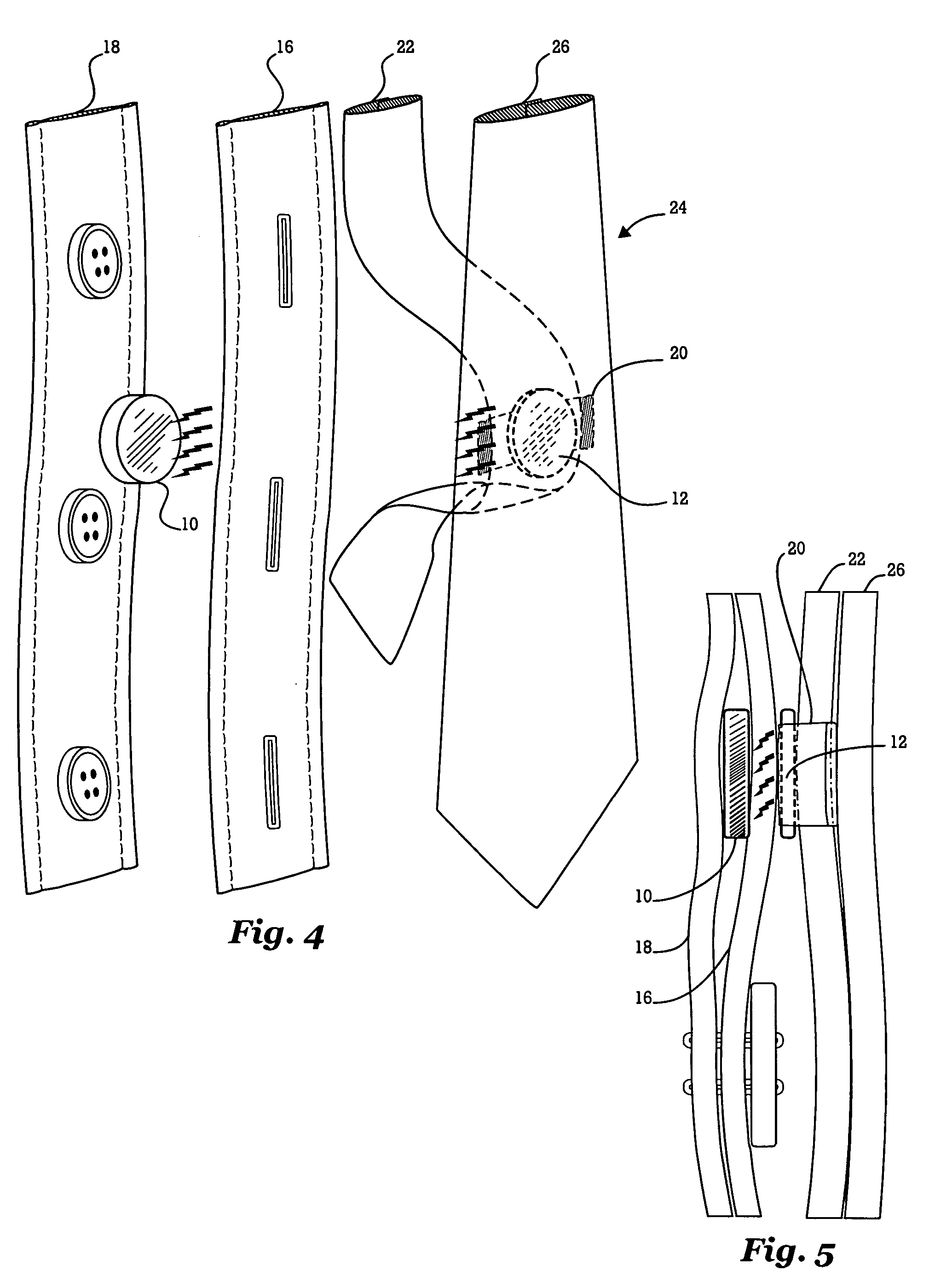

PUM


Abstract

An improved apparatus and method for holding garments, such as neckties, is disclosed. The device comprises a magnet, preferably made of a rare Earth material and magnetized to about Grade N35 or better, and a faceplate. In one embodiment, the magnet is positioned under at least a portion of the wearer's shirt while the faceplate is positioned on a portion of the wearer's necktie. The shirt and / or necktie may additionally include pockets for housing the magnet and / or faceplate. The faceplate may be decorative, and interchangeable, for prominent display in front of the necktie. Alternatively, the device may be configured to be completely hidden from view. Several means for retaining the magnet to the shirt upon separation of the garments are presented.

Description

BACKGROUND OF THE DISCLOSURE[0001]1. Field of the Invention[0002]The present invention relates in general to garment securement devices, and particularly, to necktie holders for securing one's necktie to itself and to dress shirts.[0003]2. Background Art[0004]Historically, garments worn by a person have been fastened together using buttons, belts, snaps, zippers, hook-and-loop fasteners, and the like. Permanent magnets have also been used to secure garments together, such as the magnetic button disclosed in U.S. Pat. No. 2,397,931 issued to Ellis, the magnetic button disclosed in U.S. Pat. No. 5,974,634 issued to Eisenpresser, and the magnetic attaching device disclosed in U.S. Pat. No. 5,732,451 issued to Mars. But permanent magnets made of traditional materials have not been capable of securely fastening multiple layers of clothing together due to their relatively weak magnetic field strengths. The emergence of high field strength permanent magnets in the marketplace has brought w...

Claims


Application Information

Patent Timeline
Patent Type & Authority Patents(United States)
IPC IPC(8): A41D25/04
CPCA41D25/003A44B6/00Y10T24/1959Y10T24/32A44D2203/00
Inventor SCHOENING, BRIANDORGAN, STEPHEN E.CAPESIUS, MICHAEL R.LATAWIEC, SZYMON
Owner SCHOENING BRIAN
Learn More