Gas turbine installation, cooling air supplying method and method of modifying a gas turbine installation

a technology of gas turbine and cooling air supply, which is applied in the direction of efficient propulsion technologies, mechanical equipment, machines/engines, etc., can solve the problems of increasing the temperature of the working gas, increasing the production cost, and increasing the amount of compressed air consumed to cool the components, so as to reduce the amount of compressed air extracted, increase energy efficiency, and reduce the supplying pressure of cooling air

Active Publication Date: 2008-05-20
MITSUBISHI POWER LTD
View PDF9 Cites 42 Cited by
  • Summary
  • Abstract
  • Description
  • Claims
  • Application Information

AI Technical Summary

Benefits of technology

[0006]In view of the state of the art set forth above, it is an object of the present invention to provide a gas turbine installation, a cooling air supplying method, and a method of modifying a gas turbine installation, which can reduce the amount of compressed air extracted for cooling of an exhaust plenum and which can increase energy efficiency.
[0008]According to the present invention, since the second cooling system is provided for introducing the atmosphere (ambient air) from a space on the inner peripheral side of the inner diffuser, it is possible to reduce the amount of compressed air extracted for cooling of the exhaust plenum and to increase energy efficiency. Further, since cooling air at an atmospheric pressure level can be used, supplying pressure of the cooling air can be reduced.

Problems solved by technology

Recently, however, such a rise in temperature of the working gas has increased the amount of compressed air consumed to cool the components exposed to high temperatures, e.g., the exhaust plenum and the turbine cooled vanes, to such an extent that trying to further raise the temperature of the working gas is rather contradictory to the primary intention of increasing the efficiency of gas turbines.
However, that solution greatly pushes up the production cost and is hard to realize from the practical point of view.

Method used


Image

  • Gas turbine installation, cooling air supplying method and method of modifying a gas turbine installation
  • Gas turbine installation, cooling air supplying method and method of modifying a gas turbine installation
  • Gas turbine installation, cooling air supplying method and method of modifying a gas turbine installation

Examples


first embodiment

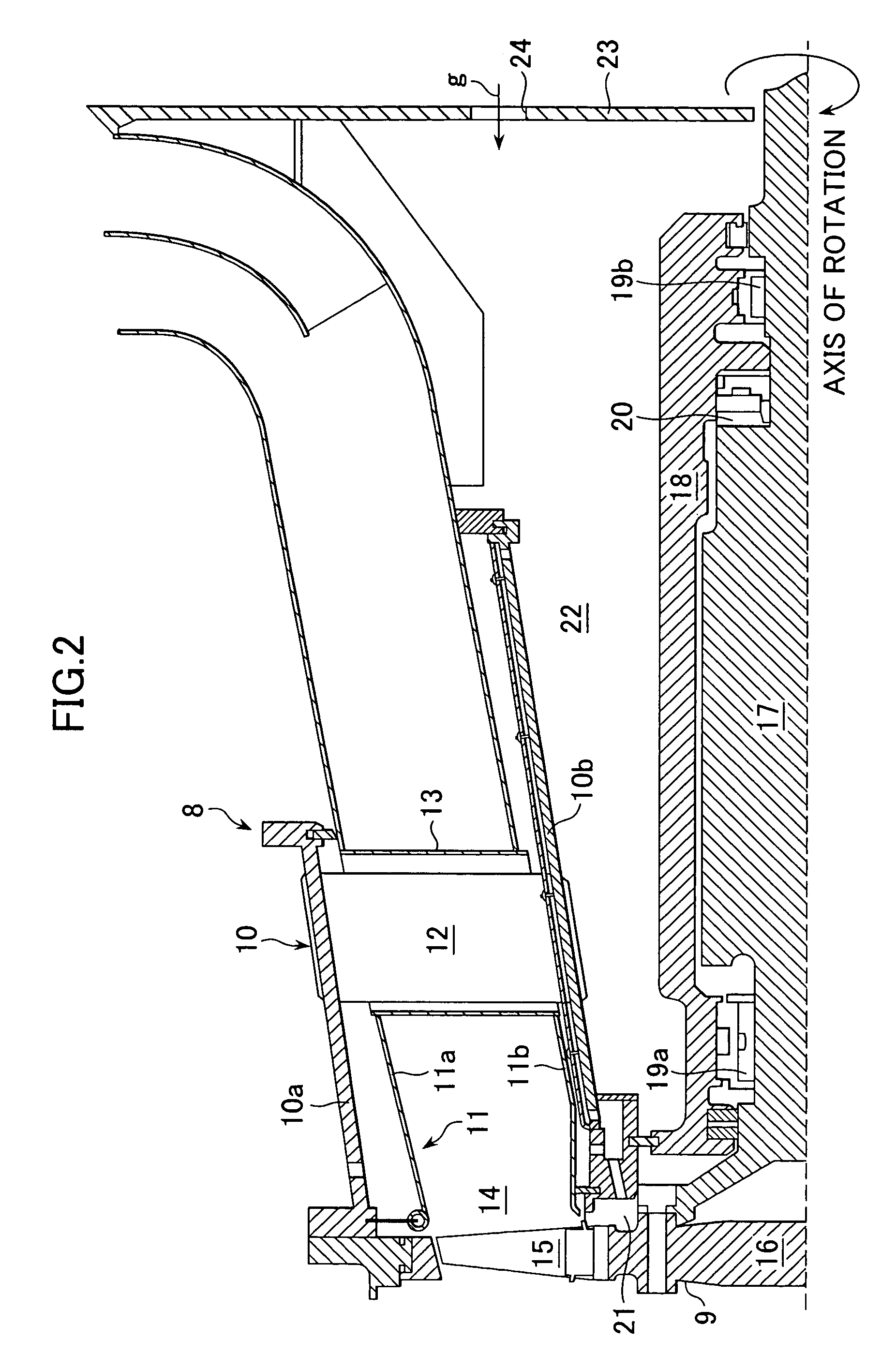
[0023]FIG. 2 is a sectional view showing a structure of an exhaust plenum and thereabout, which is provided in the gas turbine installation according to the present invention.

[0024]As shown in FIG. 2, an exhaust plenum 8 is mainly constructed by an exhaust casing 10 coupled to the downstream side of a low-pressure turbine 9 and made up of an outer casing 10a and an inner casing 10b, an exhaust diffuser 11 disposed between the outer and inner casings 10a, 10b of the exhaust casing 10 and made up of an outer diffuser 11a and an inner diffuser 11b both connected to a combustion gas outlet of the turbine, a strut 12 for coupling the exhaust casings 10a, 10b to each other, and a strut cover 13 for coupling the exhaust diffusers 11a, 11b to each other in a covering relation to the strut 12. While, in this embodiment, the inner casing 10b is extended to the rear side (right side as viewed in FIG. 2) beyond a position where the strut 12 is disposed, the present invention is not limited to s...

second embodiment

[0049]the present invention will be described below with reference to FIG. 4.

[0050]FIG. 4 is a conceptual sectional view of a cooling air system for the exhaust plenum as an essential part of a second embodiment of the gas turbine installation according to the present invention. Note that, in FIG. 4, components being similar to or having similar functions to those in FIGS. 1 to 3 are denoted by the same symbols and a description thereof is omitted here.

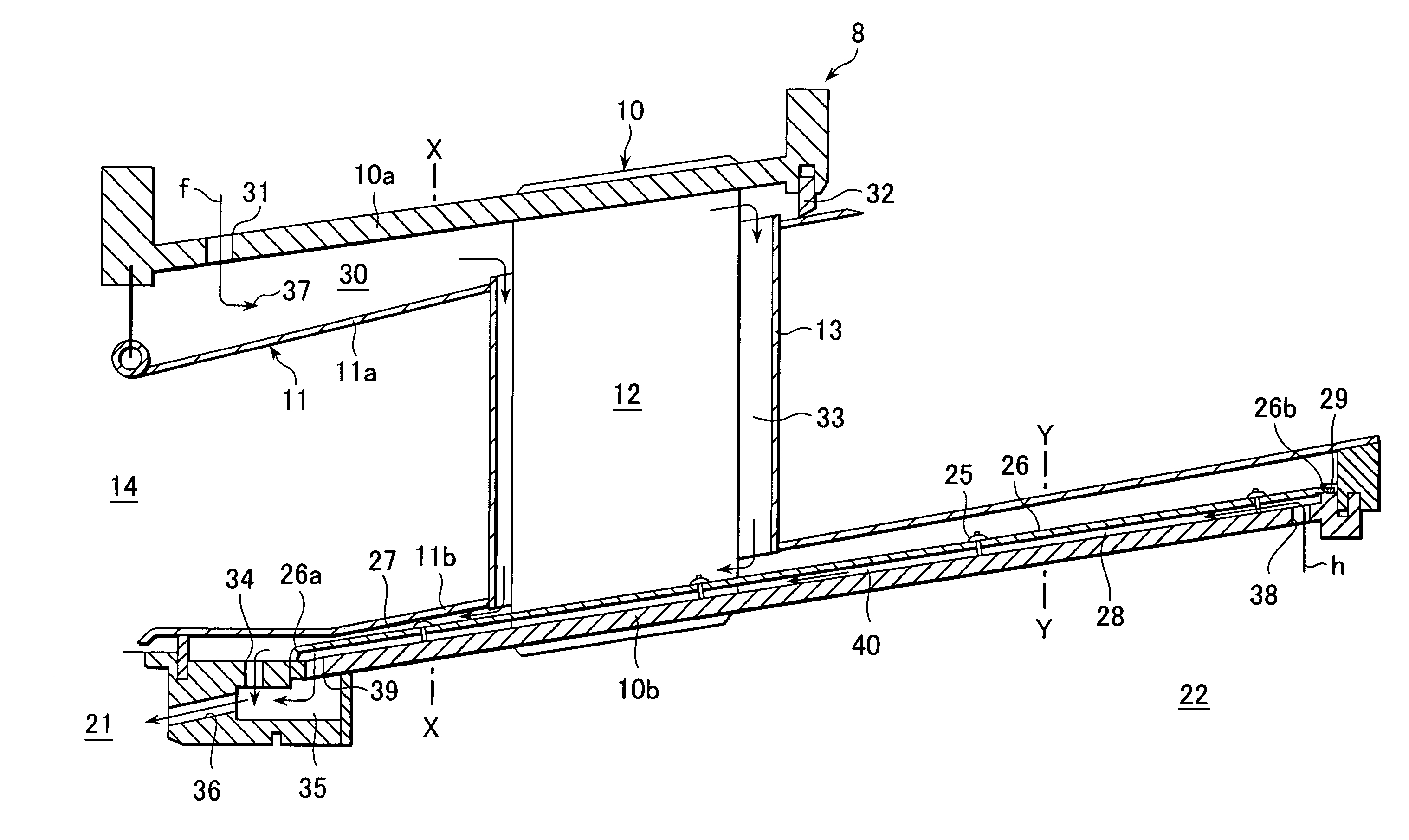
[0051]As shown in FIG. 4, in this embodiment, the space between the inner diffuser 11b and the inner casing 10b constitutes an inner diffuser space 27, and an inner casing space 28 is defined in a wall of the inner casing 10b by a plurality of in-wall channels 42 formed at intervals in the circumferential direction. The third exhaust hole 39 is formed near a front end of each in-wall channel 42, and the in-wall channels 42 is communicated with the air chamber 35 via the respective third exhaust hole 39. In this embodiment, a first coo...

third embodiment

[0056]the present invention will be described below with reference to FIG. 5.

[0057]FIG. 5 is a conceptual sectional view of a cooling air system for the exhaust plenum as an essential part of a third embodiment of the gas turbine installation according to the present invention. Note that, in FIG. 5, components being similar to or having similar functions to those in FIGS. 1 to 4 are denoted by the same symbols and a description thereof is omitted here.

[0058]As shown in FIG. 5, in this embodiment, the partition wall 26 is omitted like the second embodiment, but instead of providing the channels in the wall of the inner casing 10b to form the inner casing space 28, an annular partition plate 43 serving as an annular member is installed with a gap left relative to an inner peripheral wall surface of the inner casing 10b, thereby forming an annular inner casing space 28 similar to the first embodiment. Correspondingly, the inlet port 38 of the second cooling system 40 is formed in the a...


PUM


Abstract

The invention provides a gas turbine installation, a cooling air supplying method, a method of modifying a gas turbine installation, which can reduce the amount of compressed air extracted for cooling of an exhaust plenum and which can increase energy efficiency. The gas turbine installation comprises an exhaust plenum comprising an exhaust casing connected to the downstream side of a turbine and made up of an outer casing and an inner casing, and an exhaust diffuser made up of an outer diffuser and an inner diffuser, which are disposed between the outer casing and the inner casing; a first cooling system for introducing, from the outer peripheral side of the outer diffuser, cooling air for cooling the exhaust plenum; and a second cooling system for introducing, from the inner peripheral side of the inner diffuser, cooling air for cooling the exhaust plenum.

Description

BACKGROUND OF THE INVENTION[0001]1. Field of the Invention[0002]The present invention relates to a gas turbine installation for providing torque by combustion gas that is produced by burning compressed air together with fuel. More particularly, the present invention relates to a gas turbine installation having an exhaust plenum downstream of a turbine, to a cooling air supplying method for use in the gas turbine installation, to a method of modifying a gas turbine installation.[0003]2. Description of the Related Art[0004]In a turbine section of a gas turbine, turbine cooled vanes exposed to the highest temperature and most of other components must be cooled. For example, an exhaust diffuser of a double tube structure is generally connected to a combustion gas outlet of a turbine for the purpose of restoring the static pressure of mainstream gas. An exhaust plenum including such an exhaust diffuser is also one of the components to be cooled. The exhaust plenum usually comprises inner...

Claims


Application Information

Patent Timeline
Patent Type & Authority Patents(United States)
IPC IPC(8): F02C7/18F01D25/30F01D5/08F01D25/12F01D25/14F01D25/24F02C7/00
CPCF01D5/081F01D25/12F01D25/14F02C7/18Y02T50/60
Inventor NODA, MASAMI
Owner MITSUBISHI POWER LTD
Why Eureka
Try Eureka