
Backlight module

a backlight module and backlight technology, applied in the field of backlight modules, can solve the problems of increasing the cost of metal circuit boards b>200, consuming additional labor and space for assembling circuits, and the backlight module is expensive, so as to increase the heat dissipation efficiency of the backlight module and simplify the wire arrangement

Active Publication Date: 2008-05-20
TCL CHINA STAR OPTOELECTRONICS TECH CO LTD
View PDF9 Cites 26 Cited by
  • Summary
  • Abstract
  • Description
  • Claims
  • Application Information

AI Technical Summary

Benefits of technology

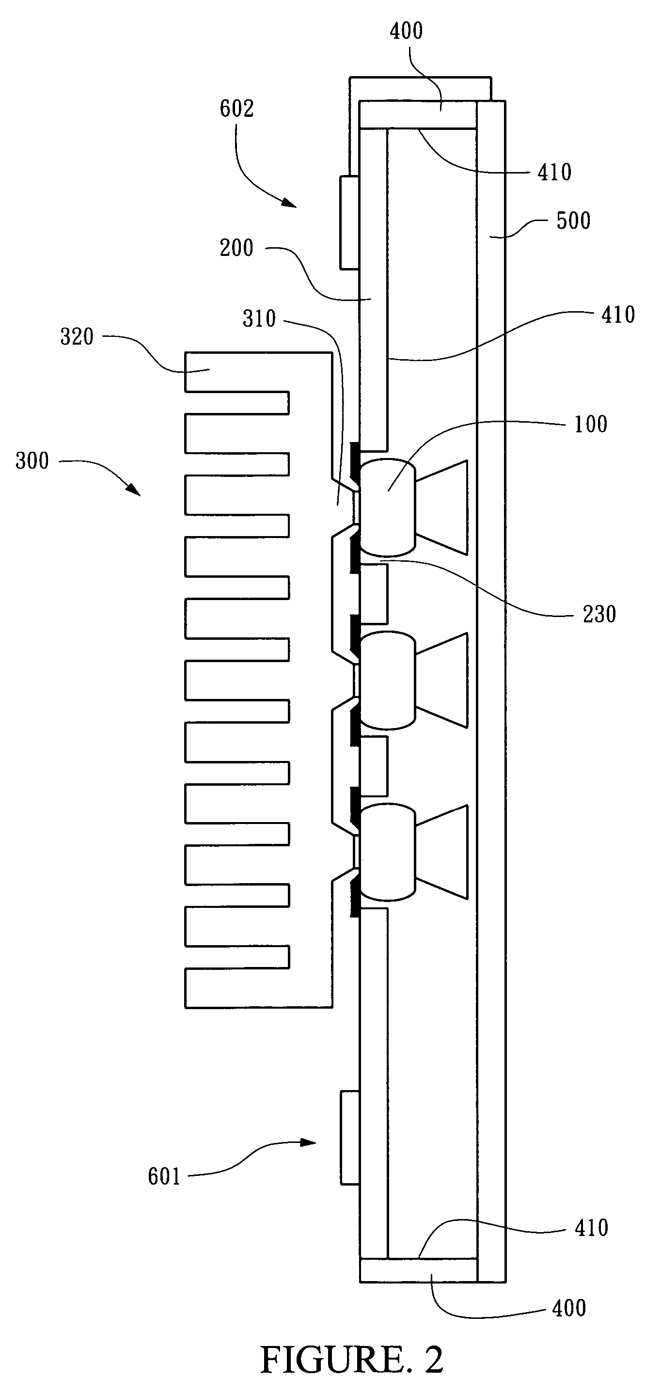
The present invention provides a backlight module that eliminates unnecessary media to increase heat dissipation efficiency. It is thin and has circuits integrated on a single baseboard to simplify wire arrangement. The heat-dispersing member adjacent to the substrate has protrusion portions and heat-dispersing fins that can transfer heat generated by the light-emitting elements to the fins directly, increasing heat-dispersing efficiency.

Problems solved by technology

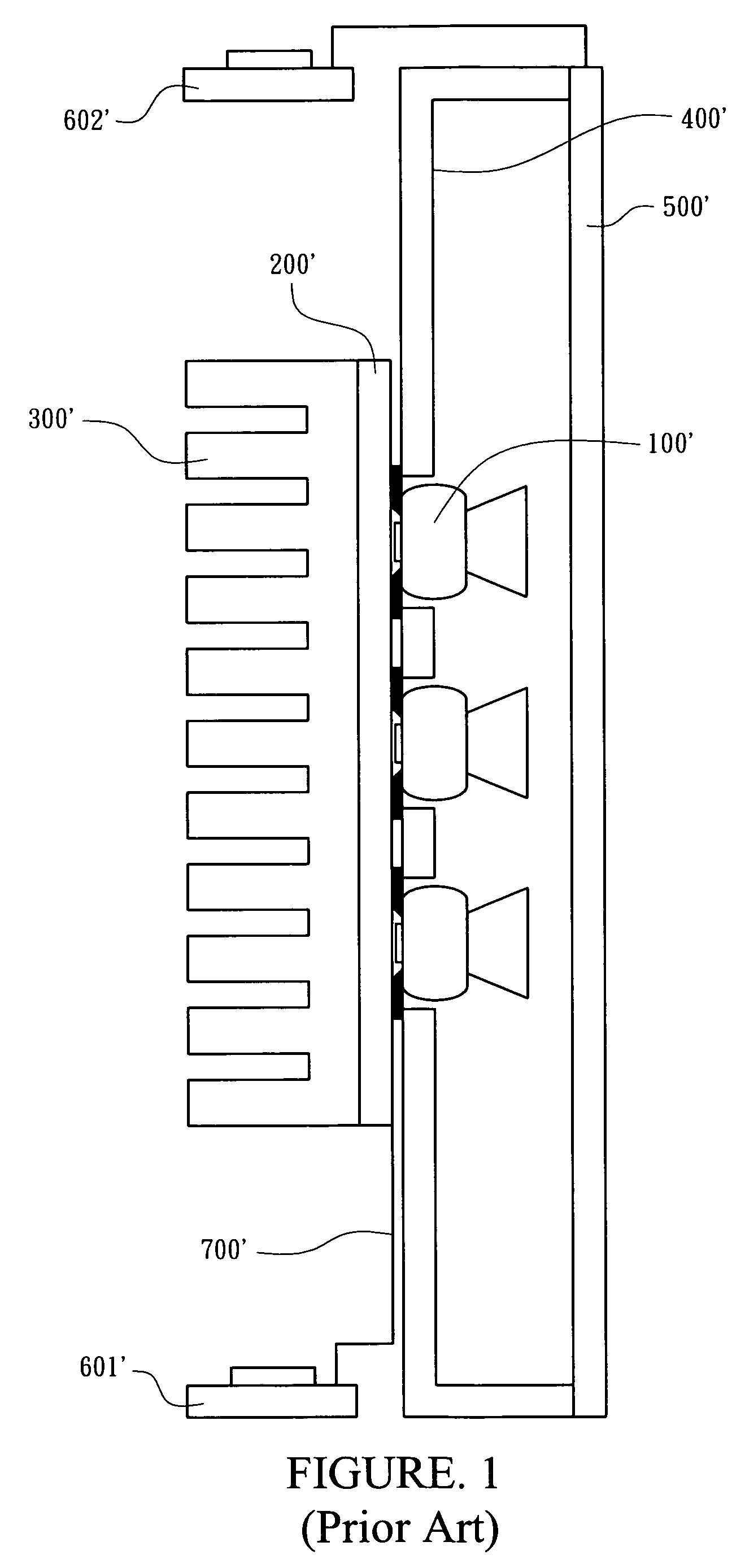
To resolve this, a substance with better thermal conductivity is applied to manufacture the metal circuit board 200′, but doing so increases the cost of the metal circuit board 200′ of the backlight module.
Assembling these circuits consumes additional labor and space to manufacture a display panel, and the complex arrangement of the wires 700′ causes the display panel to be difficult to maintain.
In addition, the arrangement of the substrate 400′ and the metal circuit board 200′ causes the display panel to be too thick to comply with customer expectations.

Method used


Image

  • Backlight module
  • Backlight module
  • Backlight module

Examples


Embodiment Construction

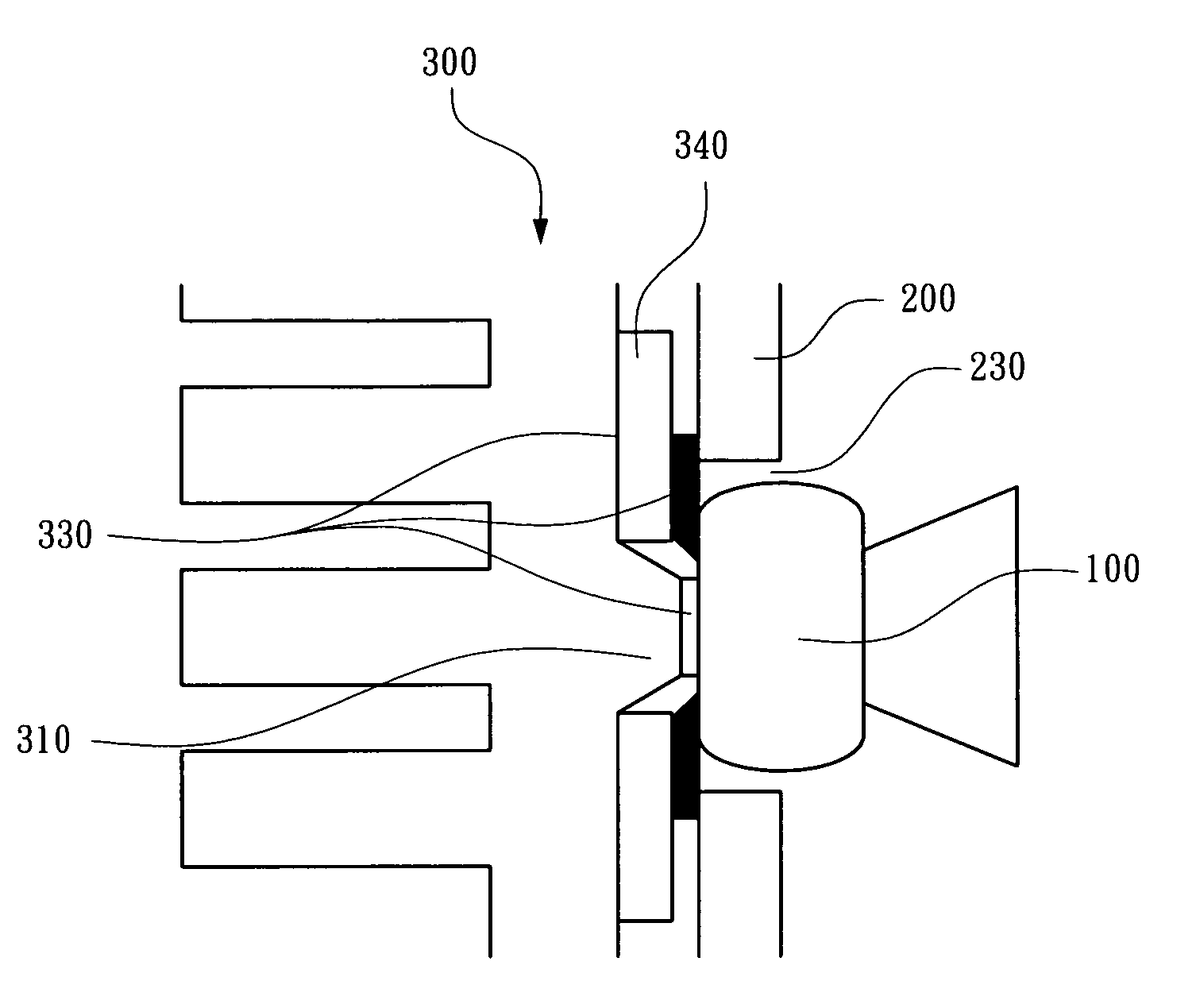
[0018]Referring to FIG. 2, a backlight module in accordance with the first preferred embodiment of the present invention is used for a display panel. The backlight module comprises light-emitting elements 100, a baseboard 200 and a heat-dispersing member 300. The light-emitting elements 100 each include at least one LED electrically connected to one surface of the baseboard 200 by an electrically connecting portion. The baseboard 200 has at least one through-hole 230 for each light-emitting element 100 to be installed therein, so that light emitted from the light-emitting elements 100 can shine on the display panel through the through-holes 230.

[0019]The heat-dispersing member 300 adjacent to the baseboard 200 has at least one protrusion 310 and at least one heat-dispersing fin 320. Each of the protrusion portions 310 contacts one of the light-emitting elements 100 installed in the through-holes 230 of the substrate 200, so that heat generated by the light-emitting elements 100 can ...


PUM


Abstract

A backlight module comprises a baseboard, at least one light-emitting element and a heat-dispersing member. The baseboard has at least one through-hole. The light-emitting element is installed in one of the through-holes and is electrically connected to a surface of the baseboard. The heat-dispersing member adjacent to the baseboard can contact the light-emitting elements directly.

Description

RELATED APPLICATIONS [0001]The present application is based on, and claims priority from, Taiwan Application Serial Number 94117121, filed May 25, 2005, the disclosure of which is hereby incorporated by reference herein in its entirety.FIELD OF THE INVENTION [0002]The present invention relates to a backlight module, and more particularly relates to a backlight module that applies a light-emitting diode (LED) as the lighting source.BACKGROUND OF THE INVENTION [0003]FIG. 1 illustrates a cross-sectional view of a backlight module in accordance with the prior art. The prior backlight module has a plurality of light-emitting elements 100′, a substrate 400′ and a metal circuit board 200′ with a heat dispersing portion 300′.[0004]The light-emitting elements 100′ comprise LEDs electrically connected to the metal circuit board 200′. The metal circuit board 200′ is fixed on one side of the substrate 400′, wherein the heat dispersing portion 300′ disposes on a surface of the metal circuit boar...

Claims


Application Information

Patent Timeline
Patent Type & Authority Patents(United States)
IPC IPC(8): F21V7/04
CPCF21V29/004G02F1/133603H05K1/0204F21V29/74H05K1/021F21Y2101/02G02F2001/133628H05K1/182H05K3/0061H05K2201/09054Y10S362/80F21V29/763F21Y2115/10G02F1/133628
Inventor KUO, TZU-SHOUCHEN, PEI-TING
Owner TCL CHINA STAR OPTOELECTRONICS TECH CO LTD
Learn More