IC socket

a socket and socket technology, applied in the direction of coupling device connection, electrical apparatus construction details, engagement/disengagement of coupling parts, etc., can solve the problems of increasing labor and unsuitability for ic sockets with pressure application covers, and achieve the effect of preventing damage to elastic contacts and insulation housings

Active Publication Date: 2008-05-20
TYCO ELECTRONICS JAPAN GK
View PDF13 Cites 17 Cited by
  • Summary
  • Abstract
  • Description
  • Claims
  • Application Information

AI Technical Summary

Benefits of technology

[0006]The present invention has been made in view of the above circumstances and provides an IC socket on which an IC package can be loaded with a small number of operations, and after the loading, the electrical connection between the pad and contact can be ensured.
[0009]It is noted here that the insulation housing is disposed off the rotation range of the crankshaft section of the lever so as to prevent the crankshaft section from applying load to the insulation housing, whereby the position of the pressure application cover can be changed with a small actuating power.
[0011]According to this aspect, the cam action is divided into two steps, thereby preventing the cam mechanism from getting bigger while securing a sufficient stroke of the cam surface.
[0013]This enables the IC package to be guided to the proper position, thus preventing damages on the elastic contacts and insulation housing caused by improperly loading the IC package.
[0014]According to the invention, it is possible to provide the IC socket in which an IC package can be loaded with a small number of operations, and after the loading, the electrical connection between the pad and contact can be ensured.

Problems solved by technology

Specifically, three operations in all, (i.e. the setting of the pressure application cover, and the manipulation of each of the pair of stoppers) must be performed, thus increasing labor.
Consequently, a direct application of the technique described in patent document 2 for a socket for IC package with pads can pose a problem in ensuring the electrical connection between the pad and contact.
In addition, in the IC socket for a PGA type package, when the mounting surface of the IC package is slid by means of the lever, a load is applied by the lever to the insulation housing in a different direction from the pressing direction by the pressure application cover, which is unsuitable for an IC socket with the pressure application cover.

Method used


Image

  • IC socket
  • IC socket
  • IC socket

Examples


Embodiment Construction

)

[0030]An embodiment of the invention will be described below with reference to the drawings.

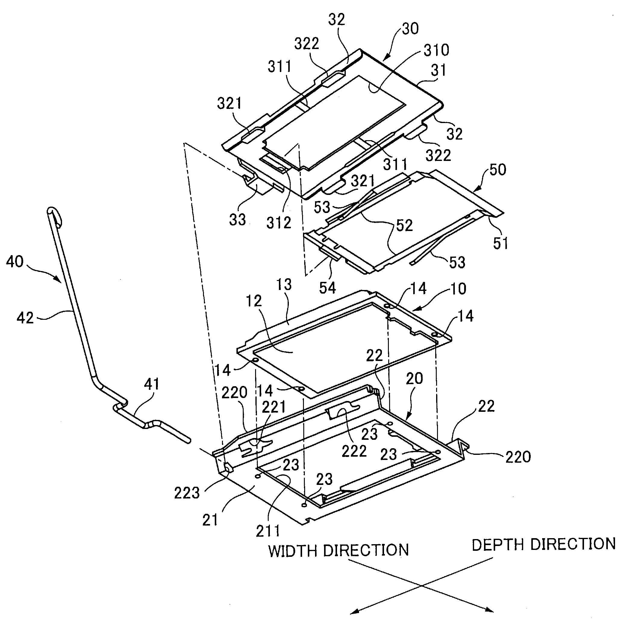
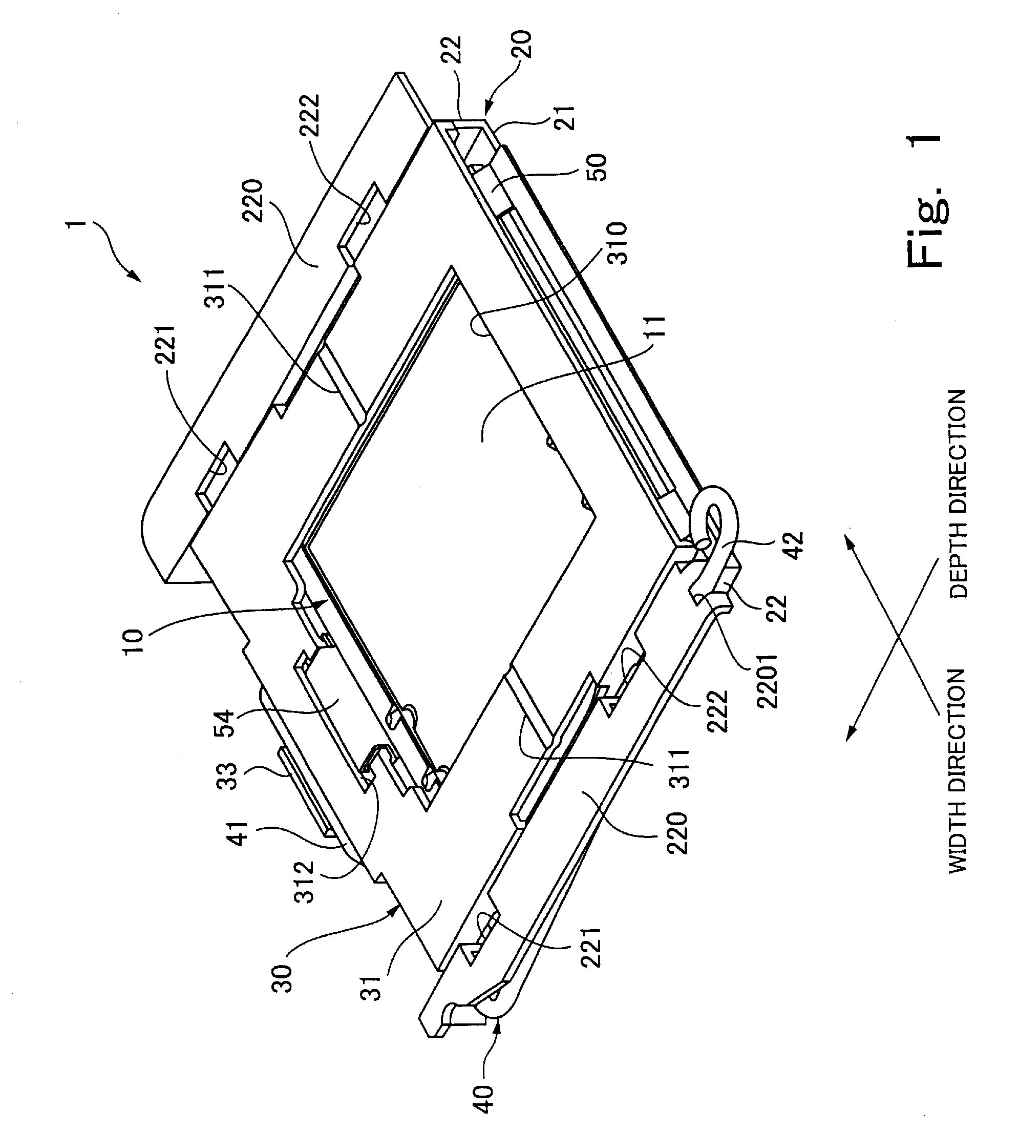
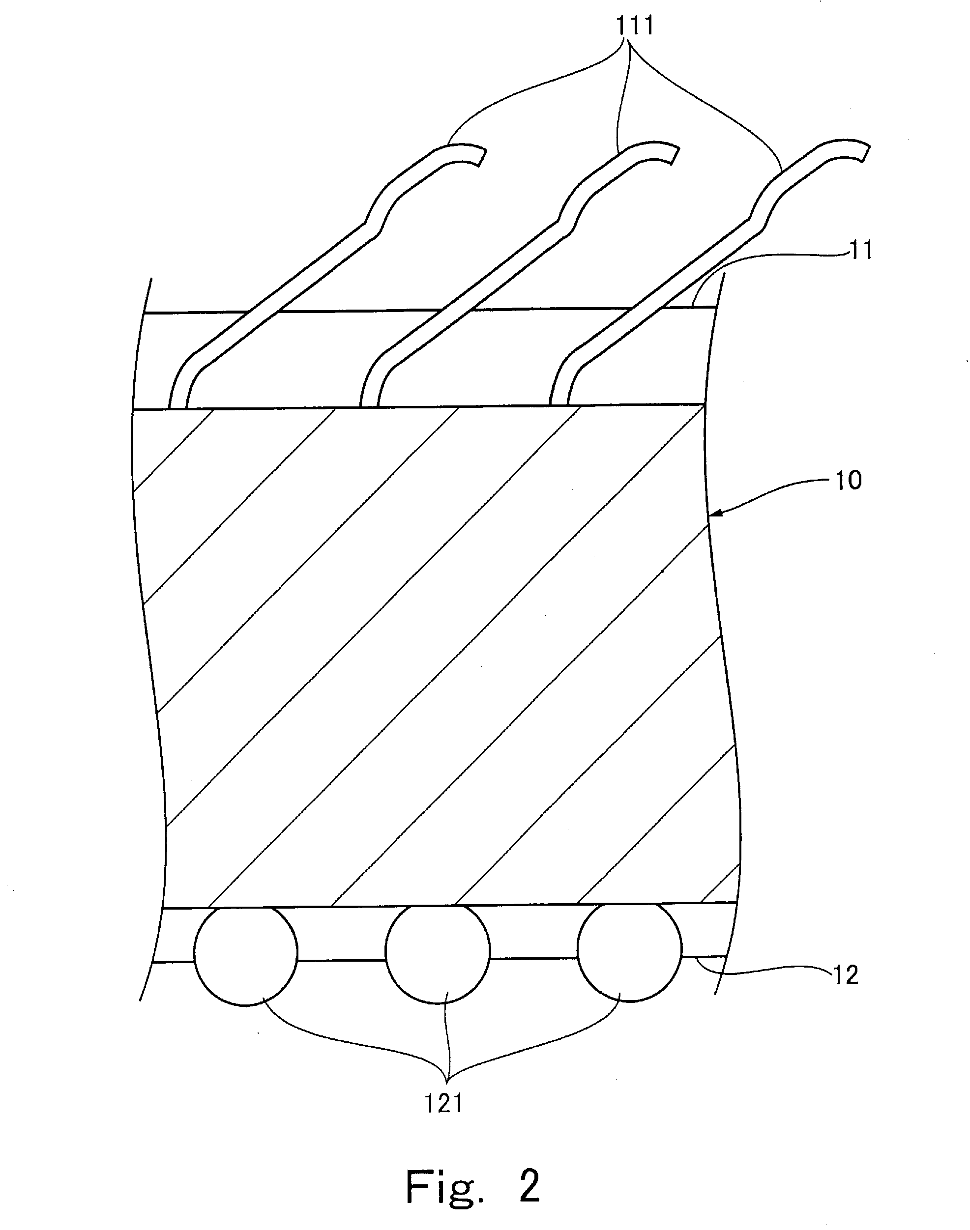
[0031]An IC socket 1, shown in FIG. 1, is a socket for an LGA (Land Grid Array) type IC package (not shown), which has a plurality of tabular pads disposed in a matrix manner on the lower face thereof. The front right side in the FIG. 1 (referred to herein as the backside) is the IC package receiving side. Hereinafter, a direction extending from the front right side to the back left side is referred to as the depth direction of the IC package 1, and a direction extending from the front left side to the back right side is referred to as the width direction of the IC package 1. The depth direction of the IC package 1 is orthogonal to the width direction of the IC package 1. The IC socket 1 includes an insulation housing 10, a load support member 20, a pressure application cover 30, a lever 40, and a guide member 50. The insulation housing 10, which may, for example, be formed of a suitable pla...


PUM


Abstract

There is provided an IC socket for an IC package having plural pads disposed in a matrix manner on the lower face thereof, on which the IC package can be loaded with a small number of operations, and after the loading, the electrical connection between the pads and contacts can be ensured. The IC socket includes: a load support member having both side walls each provided with guide grooves having cam surfaces; a pressure application cover changing position between a load position which applies load to an IC package thereby pressing the pads against elastic contacts and a no-load position, and having nail sections sliding along the cam surfaces in the guide grooves; a lever including a crankshaft section causing the nail sections to slide along the cam surfaces in the guide grooves thereby causing the pressure application cover to change position between the load position and the no-load position.

Description

RELATED APPLICATION DATA[0001]This is a continuation-in-part application of U.S. patent application Ser. No. 11 / 558,789, filed Nov. 10, 2006, now abandoned, which claims the benefit of U.S. Ser. No. 11 / 105,639, filed Apr. 14, 2005, abandoned.FIELD OF THE INVENTION[0002]The present invention relates to an IC socket including an insulation housing which has a mounting surface for mounting the lower face of an IC package, and a plurality of elastic contacts electrically connected to a substrate and provided corresponding to a plurality of pads disposed in a matrix manner on the lower face of the IC package.BACKGROUND OF THE INVENTION[0003]There are various types of IC packages having a semiconductor element packaged therein, including a type called LGA (Land Grid Array) having tabular pads disposed on the lower face thereof, a type called BGA (Ball Grid Array) having spherical pads disposed on the lower face thereof, and a type called PGA (Pin Grid Array) having lead pins disposed on t...

Claims


Application Information

Patent Timeline
Patent Type & Authority Patents(United States)
IPC IPC(8): H01R13/625H01R13/62
CPCH05K7/1053H01R13/2435
Inventor TODA, SHINSAKUKAJINUMA, SHUJI
Owner TYCO ELECTRONICS JAPAN GK
Why Eureka
Try Eureka