
System and method providing automated welding notification

a technology of automatic welding notification and system, applied in the field of computer and welding systems, can solve the problems of increasing the difficulty of controlling, maintaining, servicing and supplying multiple and isolated locations in large centers, and/or across the globe, and the need to be constantly monitored

Inactive Publication Date: 2008-05-20
LINCOLN GLOBAL INC
View PDF21 Cites 132 Cited by
  • Summary
  • Abstract
  • Description
  • Claims
  • Application Information

AI Technical Summary

Benefits of technology

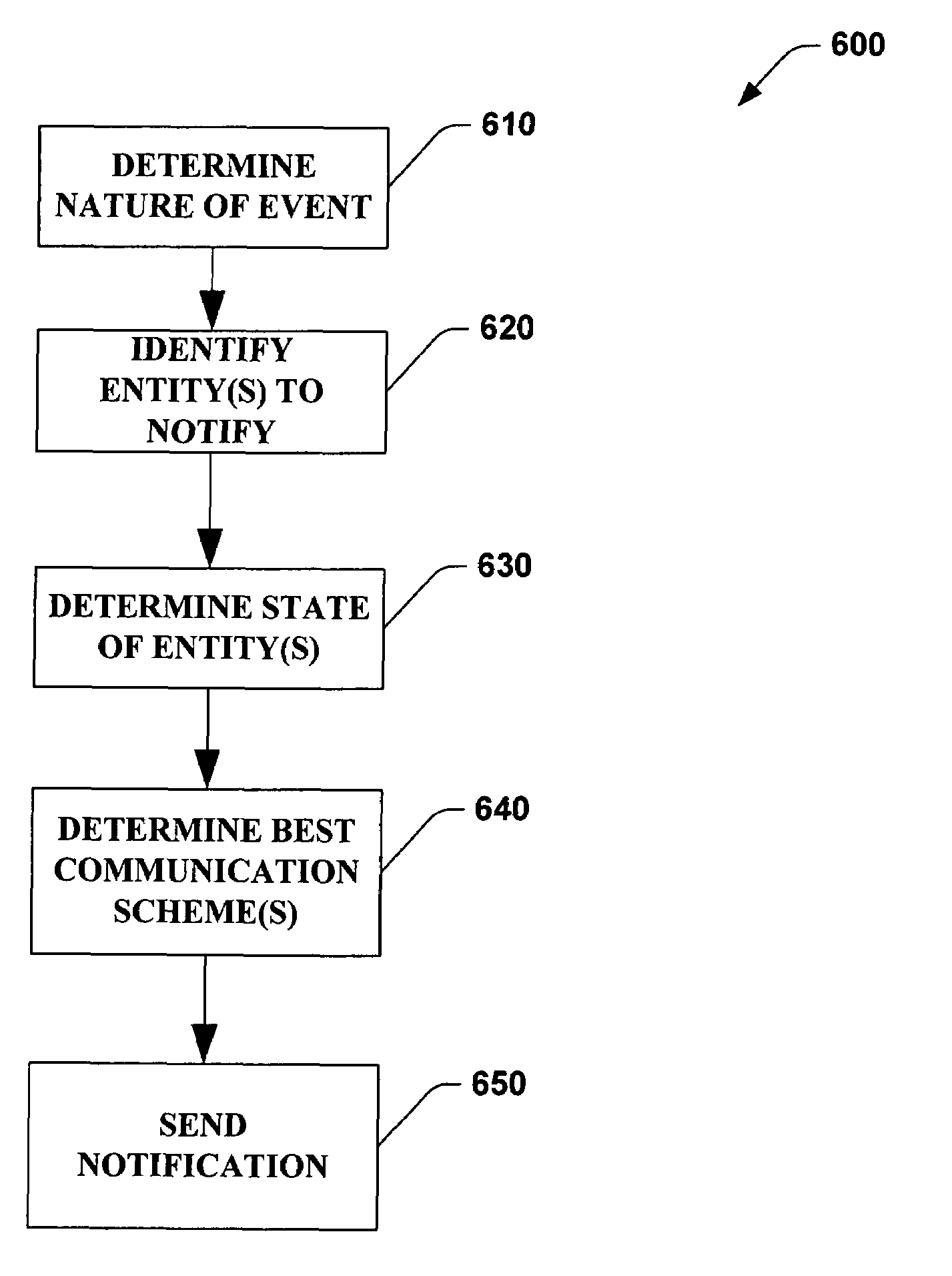
The invention is a system and method that automates the notification of welding system-related information to relevant entities. The system can detect and monitor events in the welding system and quickly notify relevant individuals or groups of people about the events. The notification can be sent via various communication modes and can include information about the event, the state of the entities, and the appropriate response. The invention can be used in different settings and applications and can use various analytical techniques to determine the importance of a notification. The technical effects of the invention include improved efficiency, better decision-making, and faster response times to welding system-related events.

Problems solved by technology

Given the nature and requirements of modem and more complex manufacturing operations however, welding systems designers, architects and suppliers face increasing challenges in regard to upgrading, maintaining, controlling, servicing and supplying various welding locations.
Unfortunately, many conventional welding systems operate in individually controlled and somewhat isolated manufacturing locations in regard to the overall joining, fabrication and / or other production process.
Thus, controlling, maintaining, servicing and supplying multiple and isolated locations in large centers, and / or across the globe, has become more challenging, time consuming and expensive.
. . ) results in situations where such variables need to be constantly monitored—which is very expensive.
Lack of monitoring can lead to catastrophic failure of machines, lines, parts, leading to potential loss of revenue.
However, it is not often practicable to have relevant entities continuously monitoring variables pertaining thereto.

Method used


Image

  • System and method providing automated welding notification
  • System and method providing automated welding notification
  • System and method providing automated welding notification

Examples


example implementation

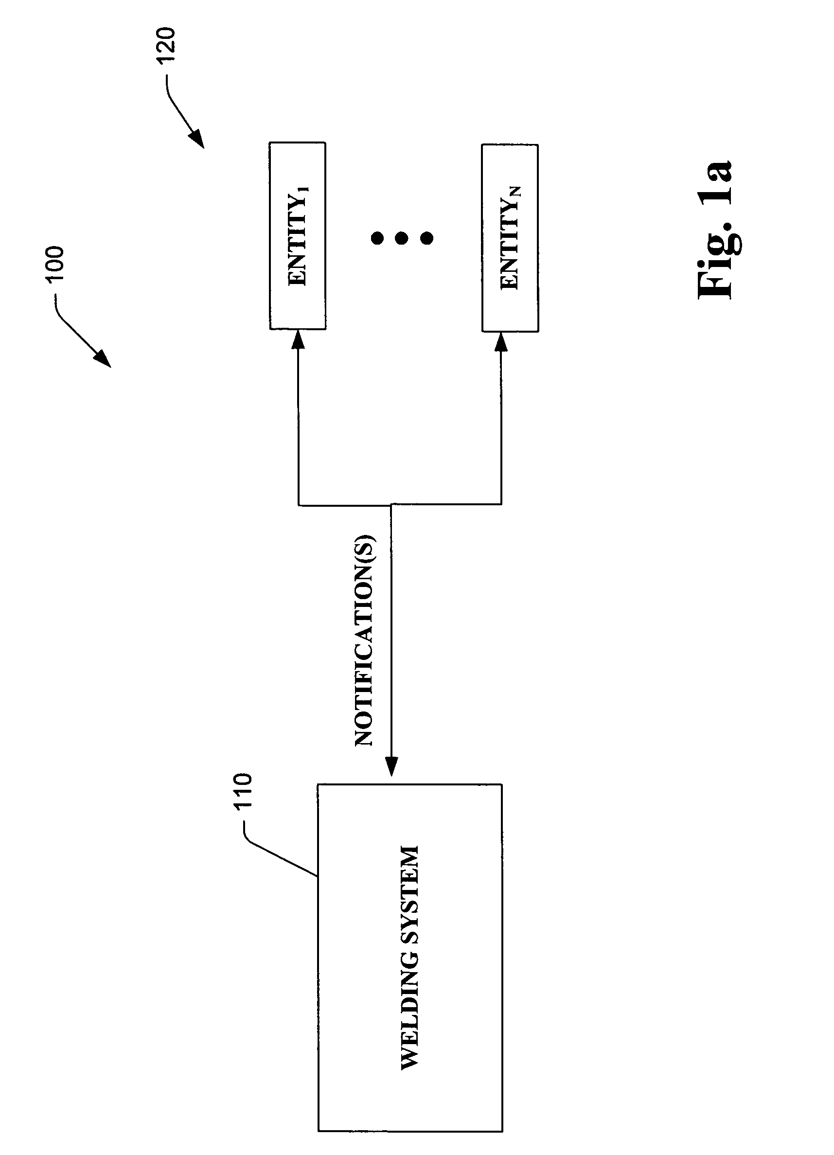
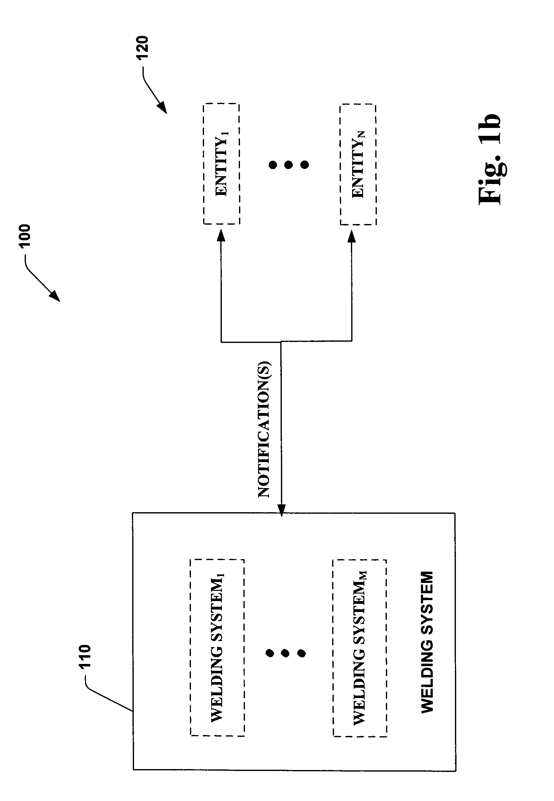
[0050]One particular example of a simple system in accordance with the invention is now provided. It is to be appreciated that this example is merely one specific manner in which to practice the invention, and the subject invention as defined by the hereto appended claims is not intended to be limited to this exemplary embodiment. The system 100 can notify entities by employing a configurable address book that is used to generate e-mail when certain events occur in the welding system 110. The system 110 includes a welder with a configurable address book that is attached to an SMTP mail server through an Ethernet network. The welder monitors itself and the welding system for certain events. When one of these events is detected, the welder will search its address book for any recipients that want to be notified when this event occurs. The address book contains configuration information associated with each address for determining which recipients to notified. If it finds one or more r...


PUM

PropertyMeasurementUnit
timeaaaaaaaaaa
currentaaaaaaaaaa
temperaturesaaaaaaaaaa

Abstract

The present invention relates to a system and method that provide for automated notification to entities (e.g., individuals, groups of individuals, computers, systems . . . ) of welding system related information. The invention provides for determination of events and / or conditions that warrant automatic notification thereof to relevant entities. The notifications are conveyed via a most appropriate subset of available communication modes available. The system identifies most appropriate entities to receive the notification about the event, and optionally determines or infers state of the entities and conveys the notification via a communication mode (e.g., text, audio, graphical, video, combination thereof . . . ) and modality (e.g., wireless, Ethernet, cable, optical, telephone, e-mail, voicemail, pager, ghosting, instant messaging . . . ) that is most suitable given context / state of the event and entities.

Description

CROSS-REFERENCE TO RELATED APPLICATIONS[0001]This application claims the benefit of U.S. patent application Ser. No. 60 / 542,891, filed Feb. 9, 2004, entitled, “SYSTEM AND METHOD PROVIDING AUTOMATED WELDING INFORMATION EXCHANGE AND REPLACEMENT PART ORDER GENERATION.” This application is also a Continuation-in-Part of U.S. patent application Ser. No. 10 / 901,658, filed Jul. 29, 2004, U.S. Pat. No. 6,924,459 entitled, “SYSTEM AND METHOD PROVIDING AUTOMATED WELDING INFORMATION EXCHANGE AND REPLACEMENT PART ORDER GENERATION”, which is a continuation of U.S. patent application Ser. No. 10 / 264,833, which was filed on Oct. 4, 2002 (now U.S. Pat. No. 6,809,292, issued Oct. 26, 2004), entitled, “SYSTEM AND METHOD PROVIDING AUTOMATED WELDING INFORMATION EXCHANGE AND REPLACEMENT PART ORDER GENERATION”, which is a continuation of U.S. Ser. No. 09 / 796,192, filed Feb. 28, 2001 (now U.S. Pat. No. 6,486,439, issued Nov. 26, 2002), entitled, “SYSTEM AND METHOD PROVIDING AUTOMATED WELDING INFORMATION E...

Claims


Application Information

Patent Timeline
Patent Type & Authority Patents(United States)
IPC IPC(8): B23K9/095B23K9/10B23K11/25B23K37/00H04M11/00
CPCB23K9/10B23K9/1062H04M11/002B23K37/00B23K11/252
Inventor KAINEC, STEPHEN M.HILLEN, EDWARD D.BLANKENSHIP, GEORGE DARYL
Owner LINCOLN GLOBAL INC
Learn More