
Battery pack

Active Publication Date: 2008-05-20
SANYO ELECTRIC CO LTD
View PDF12 Cites 22 Cited by
  • Summary
  • Abstract
  • Description
  • Claims
  • Application Information

AI Technical Summary

Benefits of technology

[0006]The present invention was developed to resolve these types of drawbacks. Thus it is a primary object of the present invention to provide a battery pack that can accurately detect battery temperature while minimizing power consumption, and can nevertheless detect battery temperature during discharge.
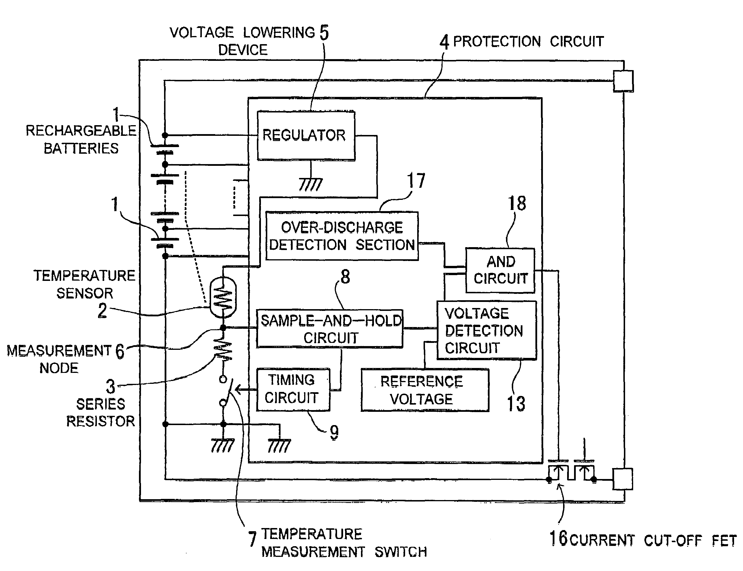
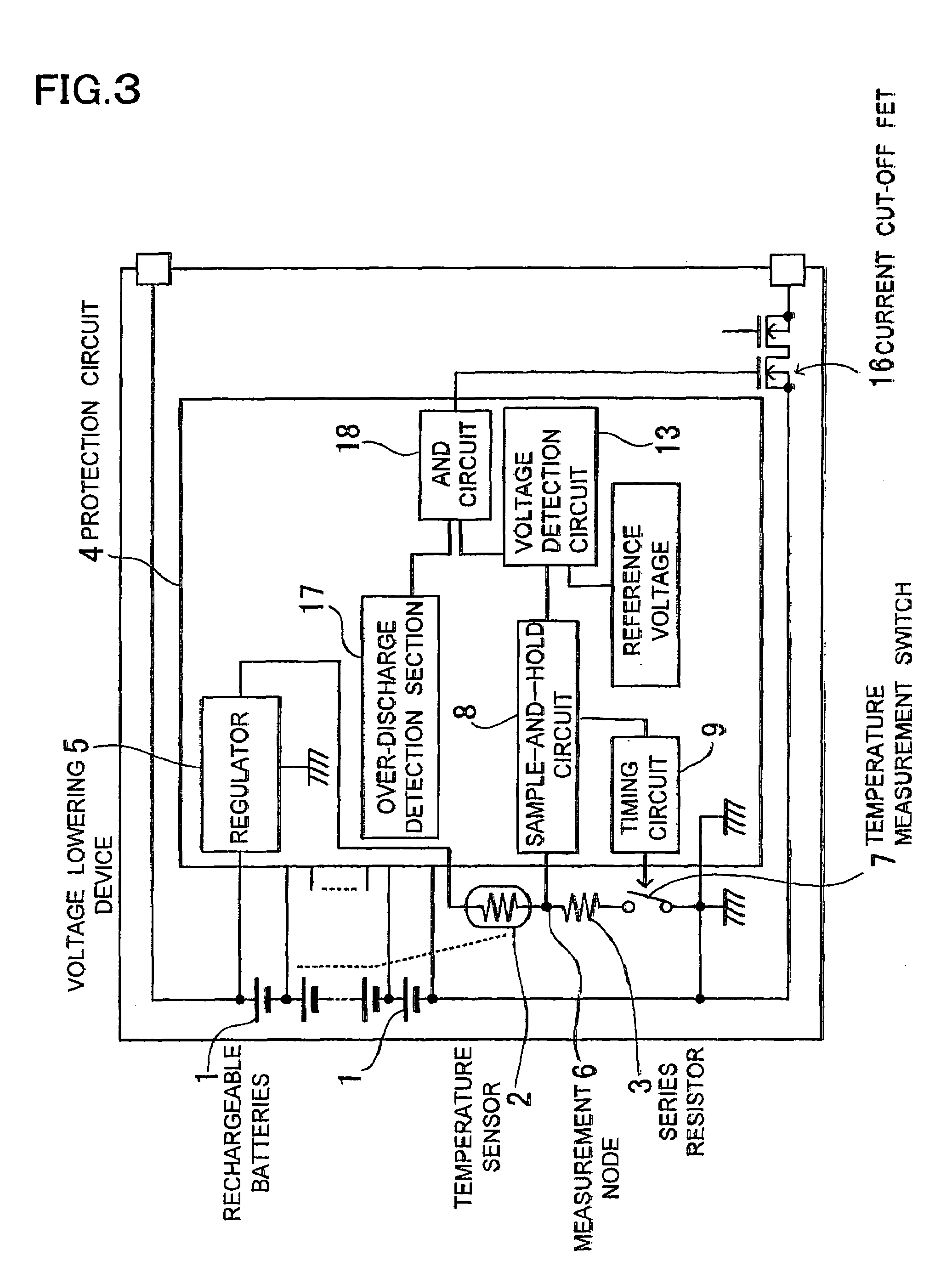
[0009]The battery pack described above has the characteristic that in addition to being able to detect battery temperature during discharge, battery power consumption is drastically reduced, and furthermore battery temperature can be accurately detected. The battery pack described above can detect battery temperature during discharge and reduce power consumption because although battery power is supplied to the temperature sensor for temperature detection, power is not always supplied to the temperature sensor. Rather power is supplied to the temperature sensor temporarily at periodic intervals, or power is supplied only when battery current has become high. In a battery pack that detects battery temperature at periodic intervals, the time which battery temperature is detected can be made markedly short compared to the time which battery temperature is not detected. Therefore, battery temperature can be detected while average power supplied to the temperature sensor from the batteries is reduced to the extreme.

Problems solved by technology

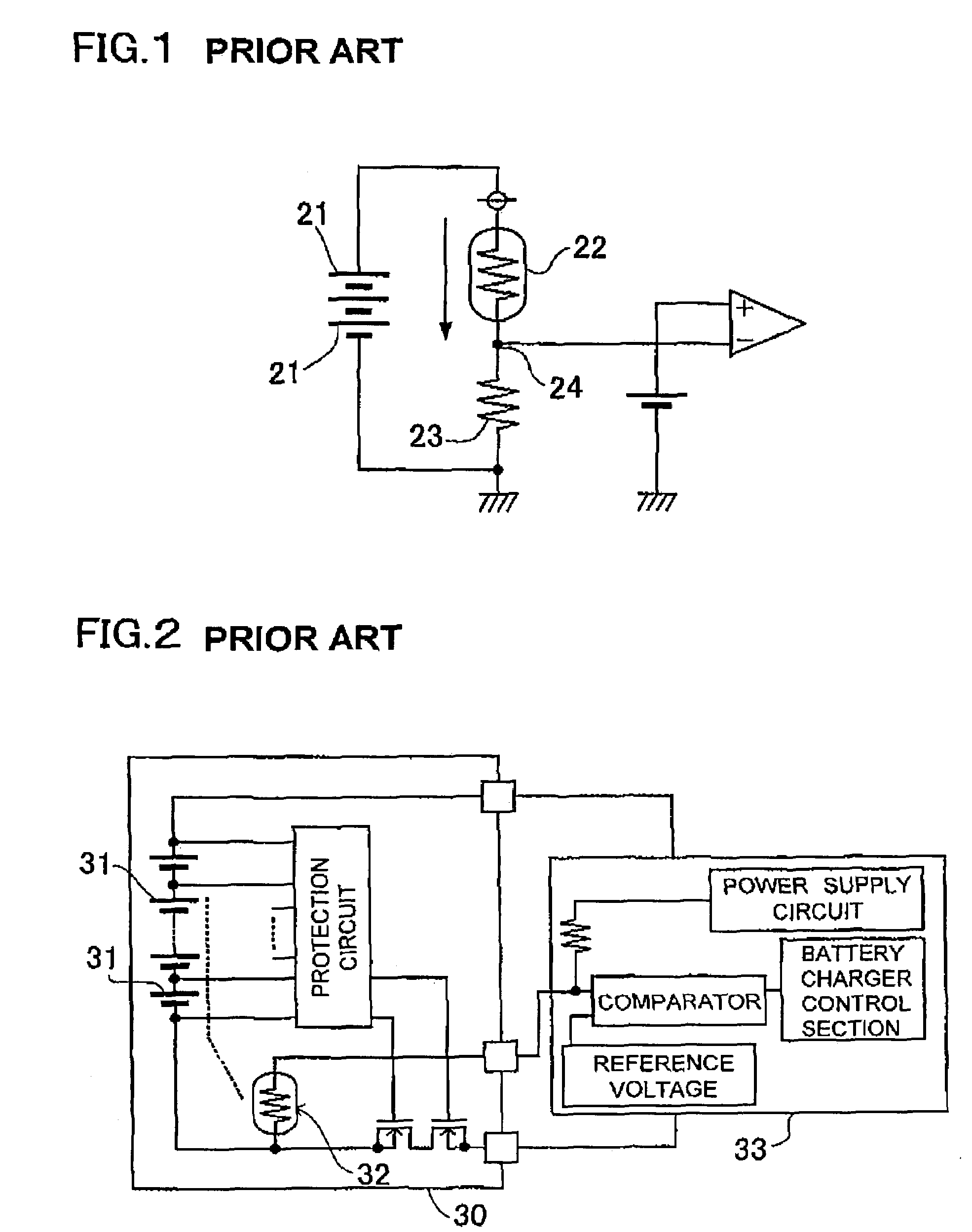
However, for proper temperature detection, power consumption of the temperature sensor, which is a thermistor, is considerably large, and the system has the drawback that battery power is wastefully consumed.
However, if the electrical resistance of the series resistor is made very large with respect to thermistor resistance, it becomes impossible to accurately detect the electrical resistance variation of the thermistor.
Consequently, for accurate detection of battery temperature, the electrical resistance of the series resistor cannot be made large, and power consumption by the thermistor circuit is high.
However, if battery temperature becomes abnormally high during battery discharge, current flowing through the batteries cannot be cut-off.

Method used


Image

  • Battery pack
  • Battery pack
  • Battery pack

Examples


Embodiment Construction

[0022]The above and further objects and features of the invention will be more fully be apparent from the following detailed description with the accompanying drawings.

[0023]A battery pack, as shown in FIGS. 3-6, is provided with rechargeable batteries 1, 51, a temperature sensor 2, 52 to detect battery temperature via change in electrical resistance, a series resistor 3, 53 connected in series with the temperature sensor 2, 52 and conducting electricity from the internally housed rechargeable batteries 1, 51 to the temperature sensor 2, 52, and a protection circuit 4, 54 to detect voltage induced by the temperature sensor 2, 52 and determine battery temperature from the electrical resistance of the temperature sensor 2, 52.

[0024]The rechargeable batteries 1, 51 are series connected lithium ion batteries. However, nickel hydrogen batteries or nickel cadmium batteries can also be used as the rechargeable batteries. Further, although the figures show four rechargeable batteries 1, 51 ...


PUM


Abstract

A battery pack that determines battery temperature via a protection circuit which detects electrical resistance change in a temperature sensor thermally joined with the rechargeable batteries. The protection circuit is provided with a timing circuit that sets timing for battery temperature detection, or it is provided with a current detection section that detects current flowing in the batteries and detects battery temperature when battery current is greater than a set current. A protection circuit, provided with a timing circuit, measures battery temperature with a fixed period. A protection circuit with a current detection section, detects battery temperature when battery current is larger than the set current.

Description

BACKGROUND OF THE INVENTION[0001]This invention relates to a battery pack containing a temperature sensor to detect battery temperature.[0002]In a battery pack containing a temperature sensor, the temperature sensor detects battery temperature that has become abnormally high. This battery pack can be used safely because current flowing in the batteries is cut-off when battery temperature becomes abnormally high and exceeds a set temperature. Since a temperature sensor's electrical resistance changes with temperature, battery temperature can be detected by detecting electrical resistance. In the NTC (negative temperature coefficient) thermistor, which is one type of temperature sensor, electrical resistance decreases with increasing temperature. An NTC thermistor can be put in contact with a battery surface, and battery temperature can be detected by detecting the electrical resistance of the NTC thermistor. A battery pack containing a temperature sensor is described, for example, in...

Claims


Application Information

Patent Timeline
IPC IPC(8): H02J7/16H01M10/48H01M50/569H02H5/04H02H7/18H02J7/00
CPCH01M10/486H02H5/042H02J7/0031H02H7/18H02J2007/004H02J2007/0039H02J7/00304H02J7/00306Y02E60/10H01M50/569H01M10/443
Inventor YAMAMOTO, HIROYOSHI
Owner SANYO ELECTRIC CO LTD
Learn More