Method and apparatus for correcting a visible light beam using a wire-grid polarizer

a technology of visible light and wire-grid polarizer, which is applied in the direction of polarising elements, optical radiation measurement, instruments, etc., can solve the problem that the optical element is capable of introducing an undesired characteristi

Inactive Publication Date: 2008-05-20
MOXTEK INC
View PDF157 Cites 55 Cited by
  • Summary
  • Abstract
  • Description
  • Claims
  • Application Information

AI Technical Summary

Benefits of technology

[0019]In addition, the invention provides an optical system to provide a light beam with a desired characteristic. A light source produces a visible light beam defining an optical train. An optical element is disposed in the optical train to create a modified beam. In addition, the optical element is capable of introducing an undesired characteristic that continuously transitions across at least a portion of the modified beam. A wire-grid polarizer is disposed in the optical train. The wire-grid polarizer has a plurality of elongated elements with at least a portion that continuously transitions to a different characteristic. The wire-grid polarizer is positioned and oriented in the optical train with the different characteristic corresponding to the undesired characteristic of the modified beam to obtain a light beam with a desired characteristic substantially across the light beam.

Problems solved by technology

In addition, the optical element is capable of introducing an undesired characteristic that continuously transitions across at least a portion of the modified beam.

Method used


Image

  • Method and apparatus for correcting a visible light beam using a wire-grid polarizer
  • Method and apparatus for correcting a visible light beam using a wire-grid polarizer
  • Method and apparatus for correcting a visible light beam using a wire-grid polarizer

Examples


Embodiment Construction

)

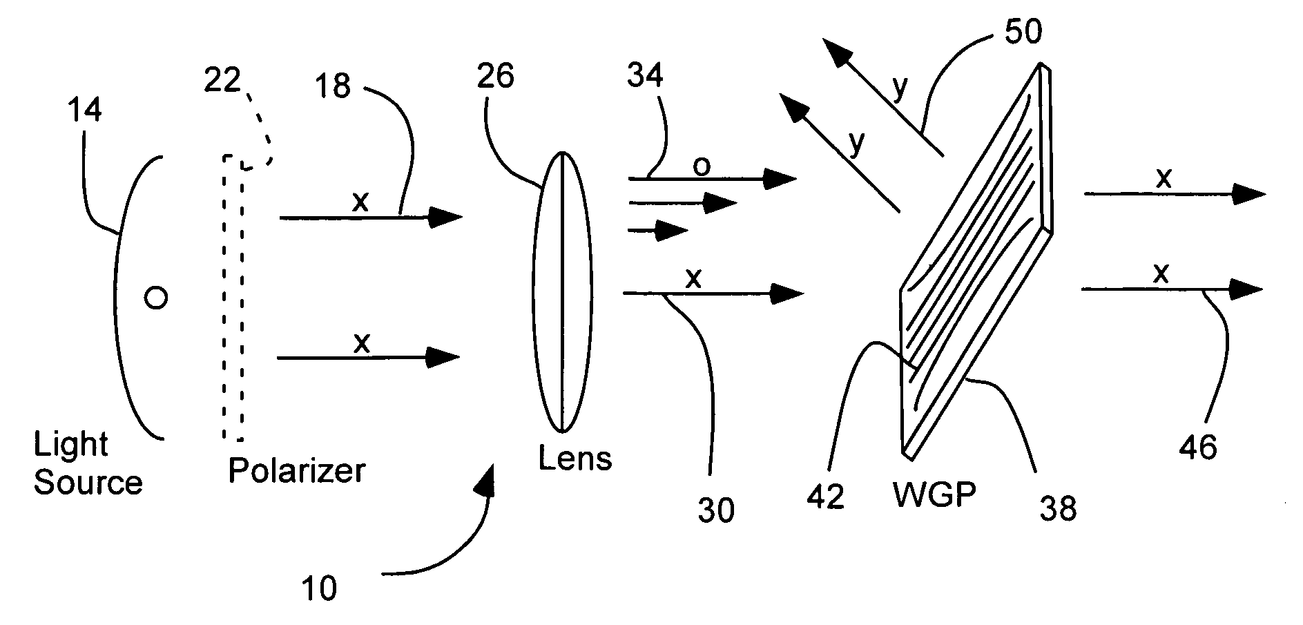
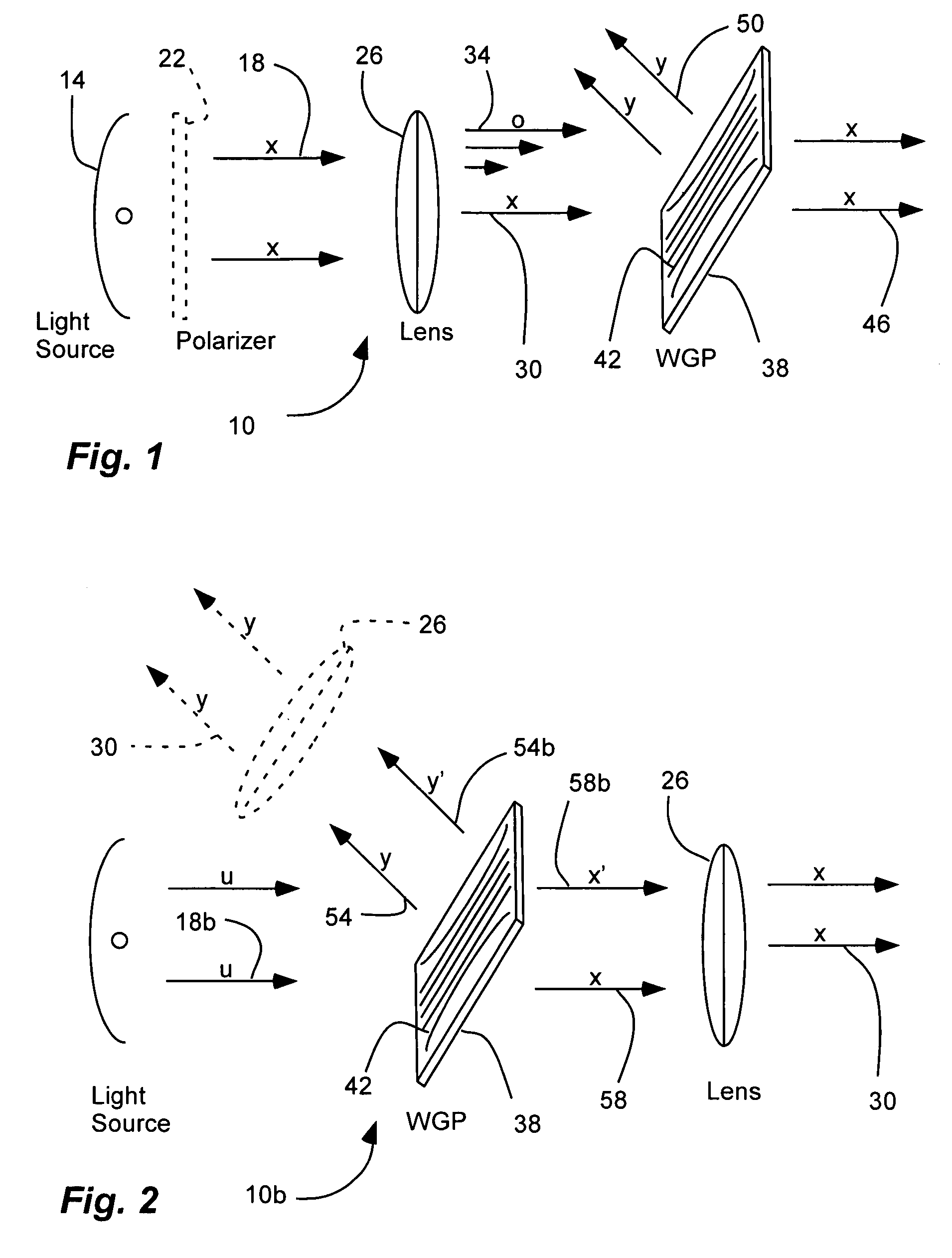
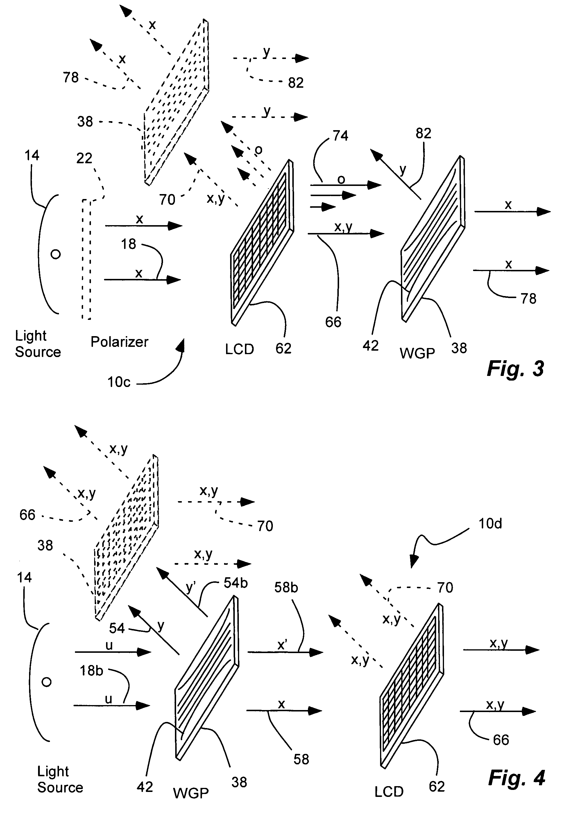
[0036]The present invention provides a method and a wire-grid polarizer for correcting or compensating for an undesirable characteristic introduced by an optic element. The undesirable characteristic can be a change in polarization state. For example, the optical element can be a lens that introduces an elliptical polarization orientation or otherwise rotates a linear polarization of a light beam, as shown in FIG. 5. As another example, the optical element can be a reflective liquid crystal array, as shown in FIG. 6. In both cases, the beam can be polarized, such as by a wire-grid polarizer with straight, elongated elements of constant thickness, width, pitch and orientation.

[0037]The present invention provides wire-grid polarizers which have been fabricated in such a way as to possess characteristics that change in a controlled manner across the optical aperture of the polarizer. The characteristics that may be changed in a controlled manner include, but are not limited to, polari...


PUM


Abstract

An optical system and method for providing a visible light beam with a desired characteristic includes a visible light source producing a visible light beam defining an optical train. An optical element is disposed in the optical train to create a modified beam, and that is capable of introducing an undesired characteristic that continuously transitions across at least a portion of the modified beam. A wire-grid polarizer is disposed in the optical train, and has a plurality of elongated elements with at least a portion that continuously transitions to a different characteristic. The wire-grid polarizer is positioned and oriented in the optical train with the different characteristic corresponding to the undesired characteristic of the modified beam to obtain a visible light beam with a desired characteristic substantially across the visible light beam.

Description

PRIORITY CLAIM[0001]This is a continuation-in-part of U.S. patent application Ser. No. 10 / 352,693, filed Jan. 27, 2003 now abandoned, which is a continuation of Ser. No. 09 / 819,565, filed Mar. 27, 2001, now abandon.BACKGROUND[0002]1. Field of the Invention[0003]The present invention relates generally to wire-grid polarizers in the visible spectrum to correct a visible light beam or compensate for another optical element.[0004]2. Related Art[0005]When certain optical elements are exposed to plane polarized light, they cause changes in the polarization state. Short of complete depolarization, they can rotate the plane of polarization, induce some ellipticity in to the beam, or both. Such changes can occur uniformly over the beam of light, or it may only occur in certain portions of the beam. In any case, the resulting beam cannot be effectively extinguished by another linear polarizer which may be required in the optical train (e.g. to generate image contrast in a liquid crystal proje...

Claims


Application Information

Patent Timeline
Patent Type & Authority Patents(United States)
IPC IPC(8): G02B5/30
CPCG02B5/3058G02B27/288
Inventor HANSEN, DOUGLAS P.PERKINS, RAYMONDTHORNE, JIMGARDNER, ERIC
Owner MOXTEK INC
Why Eureka
Try Eureka