Articulated iron cap for a hand plane

a technology of articulating iron and hand planes, which is applied in the field of woodworking tools, can solve the problems of undesirable rough cut, lack of chip breaker, shaving and wood on the frogless plane, etc., and achieve the effects of avoiding the use of frogs, being economical to manufacture, and being durable in us

Inactive Publication Date: 2008-05-27
FINE TOOLS
View PDF16 Cites 4 Cited by
  • Summary
  • Abstract
  • Description
  • Claims
  • Application Information

AI Technical Summary

Benefits of technology

[0045]There are several words that need to be defined for the purpose of this invention. This invention is entitled an Articulated Iron Cap for a Hand Plane. The word articulated simply means that the iron cap has joints or segments and is capable of having rotating parts. Another word that needs to be defined is loading. This invention refers to loading of the plane iron. Loading simply means applying pressure against the iron so as to push the lower end of the iron down and back towards the rear of the throat of the base unit with pressure as much as or greater than the pressure that would be applied as the iron is driven into the wood in which it is to cut where the wood would be pushing against the lower edge or the cutting edge of the iron. The current invention allows for the iron to be pre-loaded with a force as much as or greater than the load force of standard hand planes, thereby significantly reducing any flexing, chatter or vibrating of the iron during use. The pre-loading of the iron in the current invention allows for a much smoother cut because the iron does not flex when it is driven into the wood that is being worked. In addition, this pre-loading force allows the depth of cut to be adjusted by adding more loading force to the iron by further tightening a tensioning bolt. In fact, the depth of cut can be finely adjusted up to approximately 0.003″ (0.0762 mm) in this manner.

Problems solved by technology

One of the problems with existing planes is that frogless planes lack a chip breaker.
This can cause a “lever-effect” of a shaving and wood can be “torn” out ahead of the cut.
The result is an undesirable rough cut.
Another problem with this type of assembly of the prior art, is that the pressure from the lever cap 32 or the clamping lever assembly 40 is applied to the cap iron behind the cutting edge of the iron 28.
This creates opportunities for vibration and flex of the iron 28.

Method used


Image

  • Articulated iron cap for a hand plane
  • Articulated iron cap for a hand plane
  • Articulated iron cap for a hand plane

Examples


Embodiment Construction

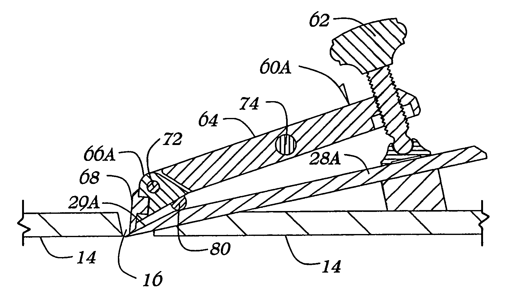
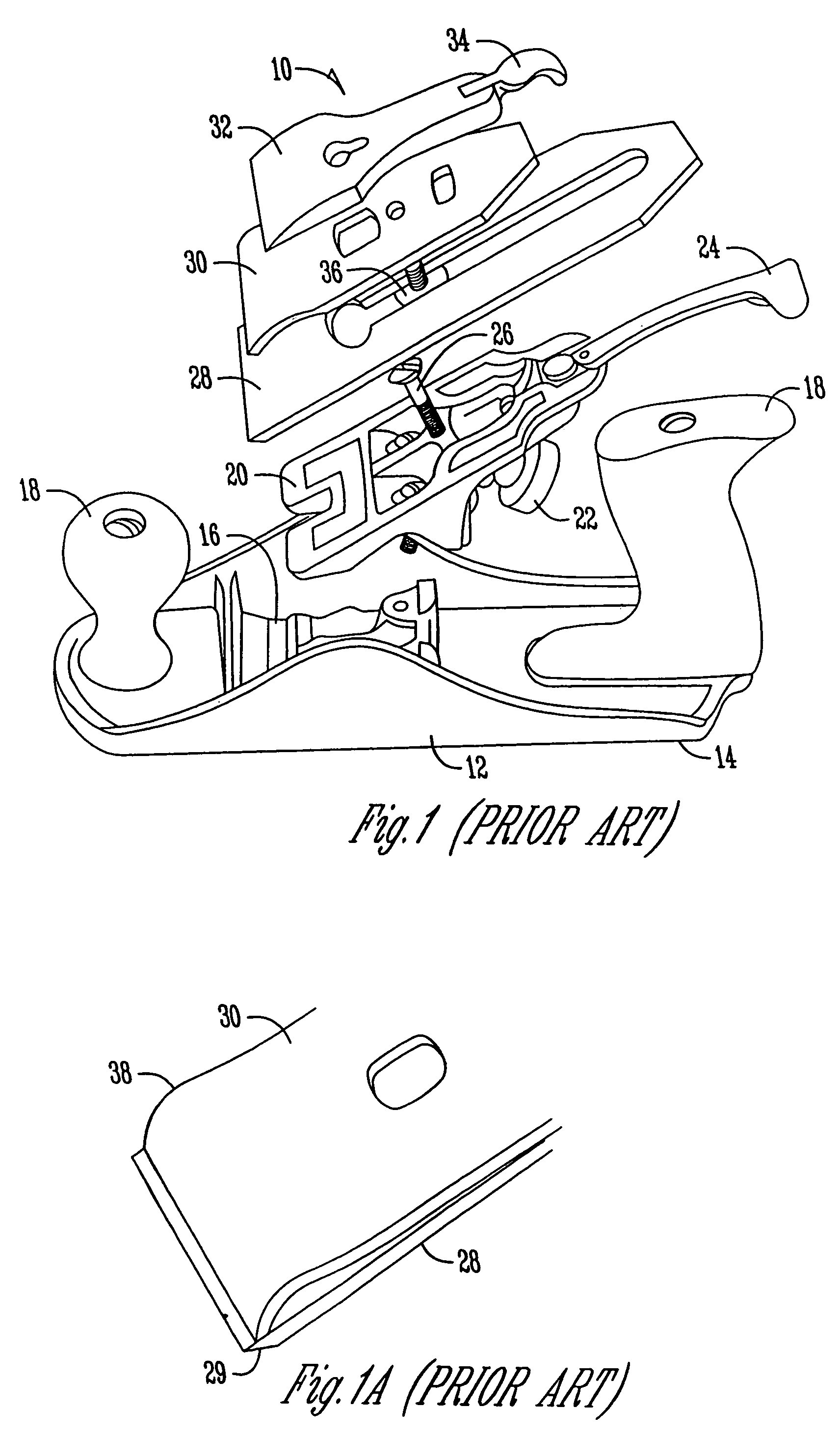
[0069]The invention is an articulated hand plane iron cap for use on a woodworking plane. One embodiment of the invention is shown in FIG. 5. This embodiment of the plane does not incorporate a frog 20, as is incorporated in the prior art, however, a frog 20 could be used with the current invention.

[0070]This embodiment of the invention is constructed with a base unit 12 in which the underside of the base unit 12 is called the sole 14. An opening in the sole 14, is a throat 16. The throat 16 can be configured as an adjustable throat, as is common in the art. Attached to the base unit 12 is also one or more totes or handles 18. The totes 18 allow the user to grip the plane so they can push or pull the plane over the wood surface to be planed however, totes 18 are not necessary. The bevel up iron 28A rests on the depth adjuster 22 and a portion of the base unit 12 and extends through the throat 16. The iron 28A is held to the base unit 12 by the articulated iron cap assembly 60A. The ...


PUM


Abstract

This invention relates to an articulated iron cap for a hand plane. The iron cap pivotally mounts to a hand plane. The iron cap for the hand plane mates to either a beveled down iron or a bevel up iron. One embodiment of the invention has a chip breaker for engaging the iron where the chip breaker pivots approximately perpendicular to the longitudinal axis of the hand plane. A nose piece on the chip breaker may be configured to extend and pivot so as to align with the grind angle on the iron. This invention places a mass near the cuffing edge of the iron which allows for preloading the iron and dampening vibration of the iron. In turn, this all creates a smoother more accurate cut and requires less effort to use.

Description

CROSS-REFERENCE TO RELATED APPLICATIONS[0001]This application is a Continuation-in-Part and claims priority under 35 U.S.C. § 119 of U.S. application Ser. No. 10 / 992,583 filed Nov. 18, 2004, which application is hereby incorporated by reference in its entirety.BACKGROUND OF THE INVENTION[0002]This invention relates to woodworking tools. Specifically, this invention relates to an articulated iron cap for a hand plane.[0003]Hand planes have been used for hundreds of years to smooth the surface of wood. A hand plane works when a woodworker pushes or pulls the plane across the surface of the wood which allows the sharp blade or the plane iron to engage the wood and shear off a thin layer of wood, thereby smoothing the wood surface.[0004]FIG. 1 shows an expanded view of a prior art hand plane. The hand plane assembly 10 has a base unit 12, in which the bottom of the base unit 12 is the sole 14. In addition, the base unit 12 has an opening in the sole 14 which is called the throat 16. Att...

Claims


Application Information

Patent Timeline
Patent Type & Authority Patents(United States)
IPC IPC(8): B27G17/02
CPCB27G17/02
Inventor ECONOMAKI, JOHN J.
Owner FINE TOOLS
Why Eureka
Try Eureka