Device for balancing a rotating part, in particular a turbojet rotor

a technology of rotating parts and rotors, which is applied in the direction of rotors, machines/engines, climate sustainability, etc., can solve the problems of difficult to put distributor nozzles in place, extra size in the axial direction upstream from the turbine that cannot be reduced, etc., and achieve the effect of reducing the weight of means

Active Publication Date: 2008-05-27
SN DETUDE & DE CONSTR DE MOTEURS DAVIATION S N E C M A
View PDF10 Cites 37 Cited by
  • Summary
  • Abstract
  • Description
  • Claims
  • Application Information

AI Technical Summary

Benefits of technology

[0005]A particular object of the invention is to avoid those drawbacks while reducing the weight of the means for fastening the balance weights to the rotary disks of such a turbine or such a turbomachine.

Problems solved by technology

That leads to extra size in the axial direction upstream from the turbine that cannot be reduced, and that makes it difficult to put a distributor nozzle into place.

Method used


Image

  • Device for balancing a rotating part, in particular a turbojet rotor
  • Device for balancing a rotating part, in particular a turbojet rotor
  • Device for balancing a rotating part, in particular a turbojet rotor

Examples


Embodiment Construction

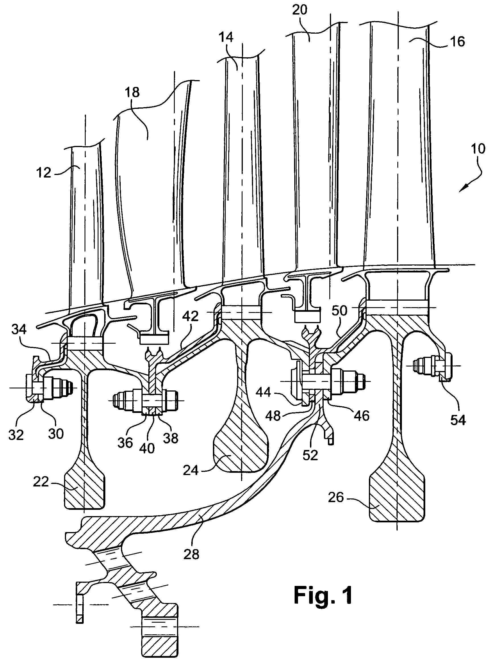
[0034]FIG. 1 is a fragmentary view of a low-pressure turbine 10 of a turbojet, having three rotor blades stages 12, 14, and 16, and two stator blade stages 18 and 20.

[0035]Using means that are not shown, the stator blades 18 and 20 are mounted via their radially outer ends to a casing of the turbojet, and the radially inner ends of the rotor blades 12, 14, and 16 are mounted on three rotor disks 22, 24, and 26 by suitable means, e.g. of dovetail or analogous type.

[0036]Each disk 22, 24, and 26 has an upstream annular flange and a downstream annular flange, these flanges serving to fasten the disks to one another and to a drive cone 28 connected to the shaft of the turbojet, and also to fasten annuluses for retaining the blade routes in the disks.

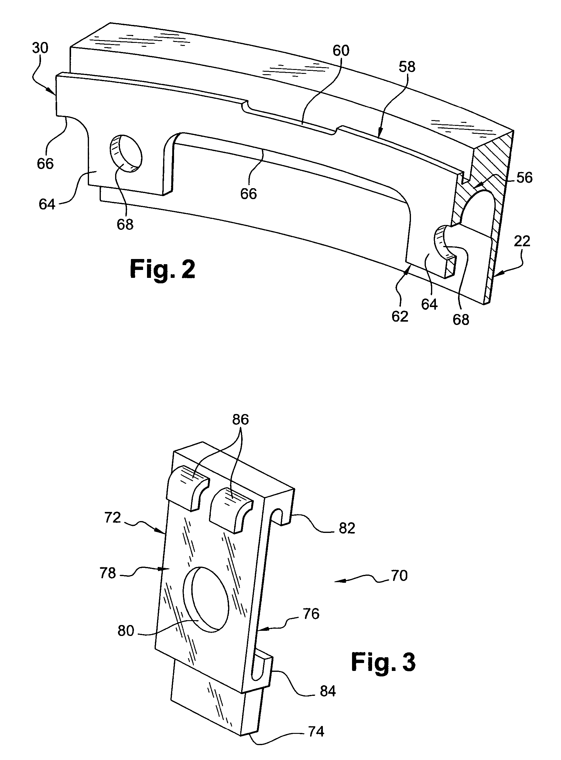
[0037]More precisely, the upstream disk 22 has an upstream annular flange 30 having bolted thereon an annular flange 32 of an annulus 34 for retaining the roots of the blade 12 on the upstream disk 22, and at least one balance weight, and a ...


PUM


Abstract

A device for balancing a rotating part, in particular a turbine rotor in a turbomachine such as a turbojet or the like, the device comprising at least one balance weight comprising engagement means for engaging it on an annular flange of the part, and locking means associated with the balance weight and with the annular flange to prevent the balance weight from moving relative to the annular flange and to block itself against moving both in rotation and in axial translation relative to the balance weight.

Description

[0001]The present invention relates to a device for balancing a rotating part, in particular a turbine rotor in a turbomachine such as a turbojet, or the like.BACKGROUND OF THE INVENTION[0002]It is well known in the art to correct the unbalance of a rotating part by means of a balance weight which is secured to the part by any appropriate means.[0003]In a low-pressure turbine of a turbojet, constituted by rotary disks carrying blades and secured to one another by annular flanges, balance weights are secured to an upstream annular flange of the upstream disk and / or to a downstream annular flange of the downstream disk, by means of bolts.[0004]That fastening technique requires there to be sufficient empty space between the upstream annular flange and the upstream disk in order to pass a tool for tightening nuts onto the bolts. That leads to extra size in the axial direction upstream from the turbine that cannot be reduced, and that makes it difficult to put a distributor nozzle into p...

Claims


Application Information

Patent Timeline
Patent Type & Authority Patents(United States)
IPC IPC(8): F01D25/00F01D5/10F01D5/02F02C7/00F04D29/66F16F15/32F16F15/34
CPCF01D5/027F16F15/34Y02T50/671Y02T50/60
Inventor CHARRIER, EMMANUELPABION, PHILIPPESOUPIZON, JEAN-LUC
Owner SN DETUDE & DE CONSTR DE MOTEURS DAVIATION S N E C M A
Why Eureka
Try Eureka