Self-balancing adjustable mounting system with friction adjustment

a mounting system and self-balancing technology, applied in the direction of threaded fasteners, machine supports, couplings, etc., can solve the problems of low degree of display position adjustment of such devices, inability to adjust display positions, and inability to move the display, etc., to achieve the effect of inhibiting undesired movement of the display

Active Publication Date: 2008-06-03
LEGRAND AV INC
View PDF53 Cites 120 Cited by
  • Summary
  • Abstract
  • Description
  • Claims
  • Application Information

AI Technical Summary

Benefits of technology

[0009]The above described configuration enables the flat panel display to be positioned in a virtually infinite number of positions within the range of travel of the semi-spherical shell within the mount. The location of the center of rotation of the display proximate the center of gravity of the display and device interface enable self-balancing so that a virtually equal effort is required to position the display in any position, and with a relatively low effort so that positioning can be accomplished by an individual user.
[0011]In an embodiment, a friction adjustment mechanism enables selective adjustment of the amount of friction between the first and second bearing portions and the frusto-spherical shell so as to enable the flat panel display to be fixed in a position to inhibit undesired movement of the display due to contact or other cause.

Problems solved by technology

The display image is often too dark or not visible at all if viewed from a significant angle.
The degree of display position adjustability of such devices is limited by the number of joints that can be economically and practically provided.
Mechanical linkages with springs are expensive to build.

Method used


Image

  • Self-balancing adjustable mounting system with friction adjustment
  • Self-balancing adjustable mounting system with friction adjustment
  • Self-balancing adjustable mounting system with friction adjustment

Examples


Embodiment Construction

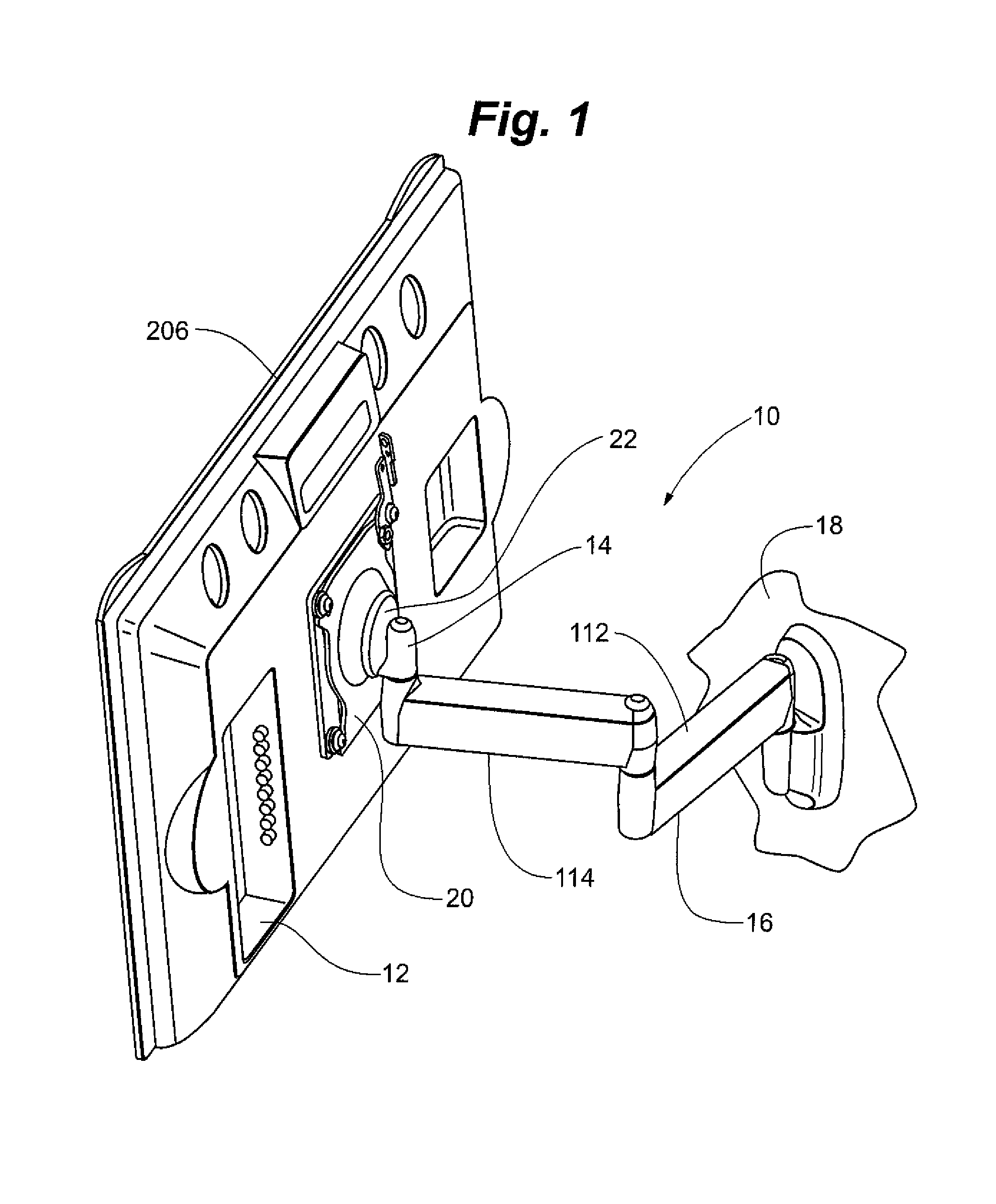
[0027]A self-balancing adjustable mounting system 10 of the present invention is depicted in FIGS. 1-8. The system 10 generally includes a flat panel display 12, a mount 14 and a support structure 16. Support structure 16 is attachable to any fixed structure such as wall 18.

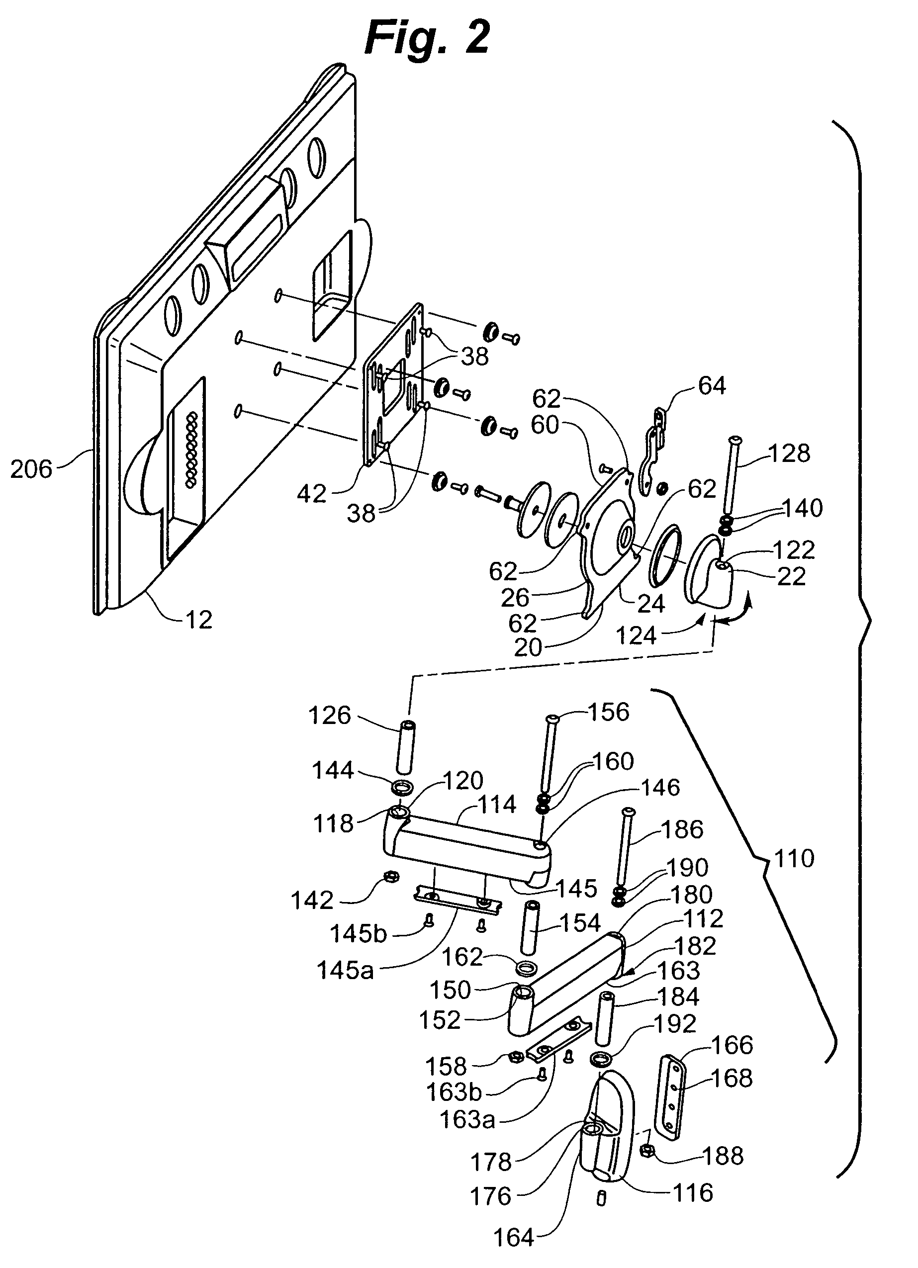
[0028]Mount 14 generally includes device interface 20 and guide structure 22. Device interface 20 generally includes a mounting plate portion 24 and a semi-spherical shell portion 26. The semi-spherical shell portion 26 has an outer surface 28, an inner surface 30 and an aperture 32 formed through the shell 26. Semi-spherical shell portion 26 has a generally constant radius of curvature 34 defined from a common center 36 over all curved portions of the shell 26.

[0029]Mounting plate 24 is removably attachable to flat panel display 12. Threaded fasteners 38 extend through slots 40 in adapter plate 42 and thread into holes 44 in flat panel display 12. Slots 40 enable adapter plate 42 to be vertically positionable on...


PUM


Abstract

A self-balancing adjustable mounting system for a flat panel display. A display interface having a hollow, frusto-spherical shell portion is attached to the flat panel display. The display interface is received in a guide structure that has a bearing portion engaging the outer surface of the frusto-spherical shell, and a second bearing portion engaging the inner surface of the frusto-spherical shell. The frusto-spherical shell is guided between the first and second bearing portions so that the flat panel display and device interface are generally rotatable about the center of the radius of curvature of the semi-spherical shell. A friction adjustment mechanism enables selective adjustment of the amount of friction between the first and second bearing portions and the frusto-spherical shell so as to enable the flat panel display to be fixed in a position to inhibit undesired movement of the display due to contact or other cause.

Description

RELATED APPLICATIONS[0001]This application is a continuation-in-part of U.S. patent application Ser. No. 10 / 449,834, entitled SELF-BALANCING ADJUSTABLE FLAT PANEL MOUNTING SYSTEM, filed May 30, 2003, now U.S. Pat. No. 7,028,961 hereby fully incorporated herein by reference.FIELD OF THE INVENTION[0002]The present invention is directed to mounts for electronic displays and more specifically to devices for mounting flat panel electronic displays such as plasma and LCD screens on a vertical structure.BACKGROUND OF THE INVENTION[0003]Flat panel displays have become an increasingly popular substitute for projection devices and CRTs. The flat panel display is typically mounted on a structure, such as a wall. Flat panel displays, especially LCD displays, are typically most clearly viewable from a position directly in front of the display. The display image is often too dark or not visible at all if viewed from a significant angle.[0004]It is thus preferable that the angle of a flat panel di...

Claims


Application Information

Patent Timeline
Patent Type & Authority Patents(United States)
IPC IPC(8): E04G3/00
CPCF16M11/02F16M11/04F16M11/041F16M11/12F16M11/14F16M13/02F16M11/2014Y10T403/1691F16M2200/028F16M2200/068Y10S248/921
Inventor DITTMER, JAY
Owner LEGRAND AV INC
Why Eureka
Try Eureka