Connecting device for a pipe or similar

a technology of connecting device and pipe, applied in the direction of hose connection, pipe/joint/fitting, sleeve/socket joint, etc., can solve the problems of reducing affecting the service life of resilient tongues, etc., to achieve reliable formation and detachment of plug connections, simple structure, and reliable

Inactive Publication Date: 2008-06-03
LINCOLN GMBH
View PDF11 Cites 10 Cited by
  • Summary
  • Abstract
  • Description
  • Claims
  • Application Information

AI Technical Summary

Benefits of technology

[0004]The invention therefore addresses a problem of implementing a connecting device of the above described type such that with simple, structure, reliable formation and detachment of a plug connection is ensured.
[0009]For a purpose of reliable arresting, it can further be advantageous to provide the at least one arresting tongue with a sharp edge on its side facing the outer wall surface of the pipe.
[0010]In simple implementation of the coupling body the first slope is formed by an annular bead encircling on the inner wall surface of the coupling body.
[0011]Of particular advantage for reliable arresting and sealing is disposition of at least two arresting tongues uniformly distributed over a circumference of the clamping collar.
[0018]For reliable seating of the actuation section in the recess of the coupling body, at least two latching tongues are advantageously distributed uniformly over a circumference of the actuation section.
[0019]Within the scope of this inventive concept it is further proposed to fabricate the function section of a metal and the actuation section of an elastically compliant material, such as a synthetic material, such that the latching tongues can be lent requisite resilient elasticity. In this embodiment of the invention a circumferential flange can be provided on the actuation section, such that a simple displacement of the actuation section, the O-ring seal and the function section as part of the clamping collar is possible from the axially outer arresting position into an axially inner starting position (release position).

Problems solved by technology

It has been found that, on the one hand, into gaps between the pipe end and clamping collar, as well as between the clamping collar and coupling body, moisture and dirt can penetrate from outside, which makes detaching the plug connection difficult and, on the other hand, when producing and detaching the plug connection scratches and like damage are generated in an outer wall surface of the pipe end, whereby leaks occur under fluid pressure obtained in the connecting device.
However, one problem is still a reliable spreading open of the arresting tongues when the clamping collar is slid in from the arresting position depicted in FIG. 1, since, on the one hand, compliance of a sealing ring at a front side of the clamping collar after ageing and, on the other hand, in absence of sufficient resilient elasticity, a reset force of the resilient tongues do not ensure an adequate spreading out force.

Method used


Image

  • Connecting device for a pipe or similar
  • Connecting device for a pipe or similar
  • Connecting device for a pipe or similar

Examples


Embodiment Construction

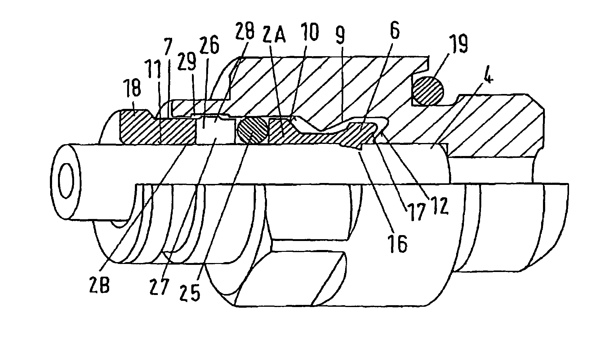
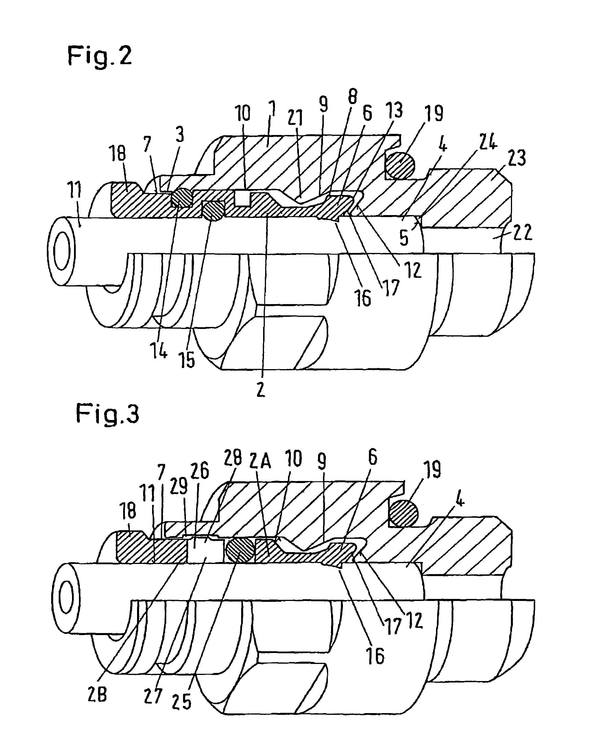
[0024]In the following the invention will be explained in further detail in its distinctive aspects in conjunction with connecting devices depicted in FIGS. 2 and 3. It may be stated in advance that in FIG. 1 the same reference symbols are utilized for corresponding structural parts of the connecting device known from prior art.

[0025]The connecting device according to FIG. 2 serves for a plug connection of a pipe 4 or the like fluid conduit with a preferably metallic coupling body 1 such that, through the connecting device a fluid such as a gaseous or liquid medium can be conducted without leakages occurring. The coupling body 1 has a substantially cylindrical recess 3 extending up to an inner shoulder serving as a stop 5 for an end of the pipe 4, which is adjoined by a channel section 22 for passage of the fluid. The channel section 22 passes through a connection piece 23 implemented for example as a threaded connection piece.

[0026]The connecting device comprises further an, also p...


PUM


Abstract

A connecting device for a pipe comprises a coupling body and a clamping collar. The clamping collar is divided into an axially inner function section and an axially outer actuation section, with a seal positioned between facing front sides of the axially inner function section and the axially outer actuation section. The seal is for sealing against an inner wall of the coupling body and against an outer wall surface of a pipe received within the clamping collar, when the clamping collar is within the coupling body.

Description

BACKGROUND OF THE INVENTION[0001]The invention relates to a connecting device for a pipe or like fluid conduit, with a coupling body and a clamping collar which can be set into a substantially cylindrical recess of the coupling body in an axially inner starting position and into which, for example after such setting into the recess, one end of the pipe to be connected can be slid, for example, until its front-side abuts a stop of the coupling body. The clamping collar comprises at its inner end at least one radially displaceable arresting tongue, which, when the pipe, and therewith the clamping collar, is slid back in a direction of a recess inlet, for example under pressure building up in the pipe coupling, up into an axially outer arresting position, can be pressed radially inwardly and with its inner side into engagement with an outer wall surface of the pipe through cooperation of an outer side of the arresting tongue with a first slope, radially slanting in the direction of the...

Claims


Application Information

Patent Timeline
Patent Type & Authority Patents(United States)
IPC IPC(8): F16L21/06F16L33/22F16L37/092
CPCF16L33/227F16L37/0925F16L37/0927
Inventor PALUNCIC, ZDRAVKO
Owner LINCOLN GMBH
Why Eureka
Try Eureka