Ultrasonic transducer, ultrasonic speaker, and method of controlling the driving of ultrasonic transducer

a technology of ultrasonic transducers and ultrasonic speakers, which is applied in the direction of ultrasonic/sonic/infrasonic diagnostics, mechanical vibration separation, application, etc., can solve the problems of generating waveform distortion, difficult to improve reproduction sound quality, and difficult to control the reproduction range, so as to reduce the audible components, suppress the asymmetrical positive and negative distortion of the output vibration waveform, and the effect of high-directivity speakers

Inactive Publication Date: 2008-06-03
SEIKO EPSON CORP
View PDF12 Cites 18 Cited by
  • Summary
  • Abstract
  • Description
  • Claims
  • Application Information

AI Technical Summary

Benefits of technology

[0023]An advantage of the invention is to provide an ultrasonic transducer, an ultrasonic speaker, and a method of controlling the driving of the ultrasonic transducer, in which the asymmetrically positive and negative distortion of the outputted vibration waveform is suppressed to decrease audible components generated directly from the transducer, thereby achieving a high-directivity speaker.
[0024]According to a first aspect of the invention, there is provided an electrostatic ultrasonic transducer including a diaphragm having a conducting layer and a pair of first and second fixed electrodes opposed to the corresponding surfaces of the diaphragm, the pair of fixed electrodes having a plurality of through holes in corresponding positions, wherein a DC bias voltage is applied to the conducting layer of the diaphragm and an alternating current signal is applied between the first and second fixed electrodes to generate an ultrasonic wave. Part of the pair of fixed electrodes includes a driving fixed electrode for driving the ultrasonic transducer, and the other part includes a detecting fixed electrode for detecting the amplitude of the diaphragm. The ultrasonic transducer includes a control unit that controls the vibration of the diaphragm so that the amplitude of the diaphragm is proportional to the input signal on the basis of the amplitude of the diaphragm detected by the detecting fixed electrode.
[0025]With such a structure, part of the pair of first and second fixed electrodes which are opposed to the corresponding surface of the diaphragm is used as a driving electrode and the other part as a detecting electrode (electrostatic sensor). The signal to be applied to the respective driving electrodes of the first and second fixed electrodes are feedback-controlled (the gain is controlled) so that the diaphragm vibrates symmetrically on both sides (symmetrically for positive and negative values of the input signal).
[0026]Thus, the push-pull electrostatic ultrasonic transducer is allowed, even if a process error in manufacturing, a positioning error, and variations in electrical characteristics occur between the pair of fixed electrodes opposed to the diaphragm of the transducer, to suppress asymmetrical positive and negative distortion of the output vibration waveform, reducing the audible component that is generated directly from the transducer, thus achieving a higher-directivity speaker.
[0027]It is preferable that each of the pair of fixed electrodes be an array of a plurality of electrodes that is insulated from one another, part of the electrode array serving as the driving fixed electrode, and the other part of the fixed electrode serving as the amplitude-detecting fixed electrode.
[0028]With such a structure, the fixed electrode is an array of a plurality of electrodes that is insulated from one another. Accordingly, the ultrasonic transducer can be constructed of a combination of electrode arrays. Ultrasonic transducers of various sizes and shapes can therefore be manufactured depending on the combination of the electrode arrays. The electrode arrays serving as the detecting fixed electrodes can be arranged in desired positions. Also, multiple detecting fixed electrodes can be provided.

Problems solved by technology

When a modulated wave (sound wave) generated by modulating the amplitude of a high sound-pressure ultrasonic carrier wave by an audio-range signal is radiated into air, the sound speed is high at a high sound pressure and low at a low sound pressure, generating distortion in the waveform as the sound wave propagates in the air.
The related-art superdirectivity speakers, however, are regarded as having a lower reproduction sound quality than loud speakers, so that they are used only for audio application such as local announcement and exhibition commentary.
Thus, the resonant transducer has a narrow-band frequency response with a limited drive frequency, thus having the problems that it is difficult to improve the reproduction sound quality and to control the reproduction range.
It also has the problem of being sensitive to an excessive input, tending to damage the elements, thus requiring some cautions.
On the other hand, it has the disadvantage of having an output waveform with large distortion because its vibration conductive component is only the electrostatic attracting force and the elastic restoring force of the diaphragm.
On the other hand, it has the disadvantage of having difficulty in obtaining a high sound pressure, because of a low aperture ratio since sound waves are outputted through a through hole in the fixed electrode.
When the electrostatic ultrasonic transducer is used for a superdirectivity speaker, even when an ideally amplitude modulated wave in an ultrasonic band is inputted to the speaker, if the asymmetrically positive and negative distortion component of the waveform (carrier wave) outputted from the transducer is large, the distortion component becomes an audible component, so that, in addition to the ultrasonic component, the audible sound is outputted directly from the speaker, thus posing the specific problem of decreasing the directivity in audibility.
This is because the electrostatic transducer has the sound-pressure characteristics of a wide frequency band (even if an audible sound itself is inputted directly, a good sound pressure can be outputted), which is a problem peculiar to a transducer with wide-band frequency characteristic.
Accordingly, the super-directivity speaker using the related-art push-pull transducer, if it has an error in manufacturing, a positioning error, and variations in electrical characteristics, generates asymmetrically positive and negative distortion in the output waveform, resulting in a decrease in audible directivity.

Method used


Image

  • Ultrasonic transducer, ultrasonic speaker, and method of controlling the driving of ultrasonic transducer
  • Ultrasonic transducer, ultrasonic speaker, and method of controlling the driving of ultrasonic transducer
  • Ultrasonic transducer, ultrasonic speaker, and method of controlling the driving of ultrasonic transducer

Examples


Embodiment Construction

[0081]Preferred embodiments of the invention will be described hereinbelow with reference to the drawings.

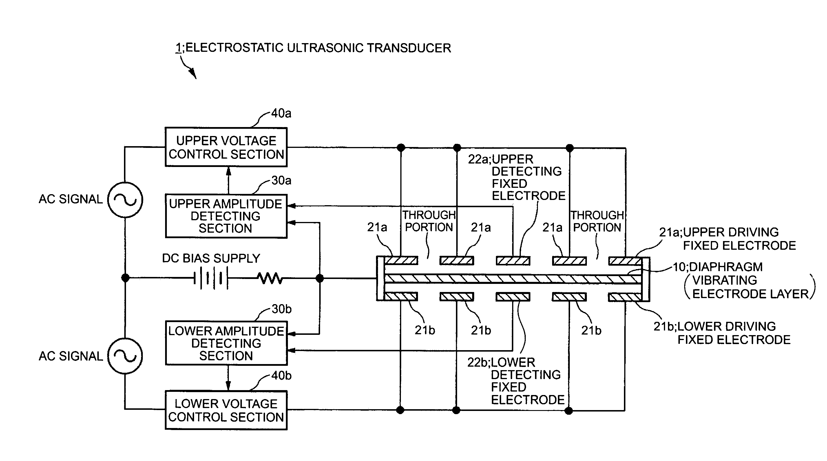
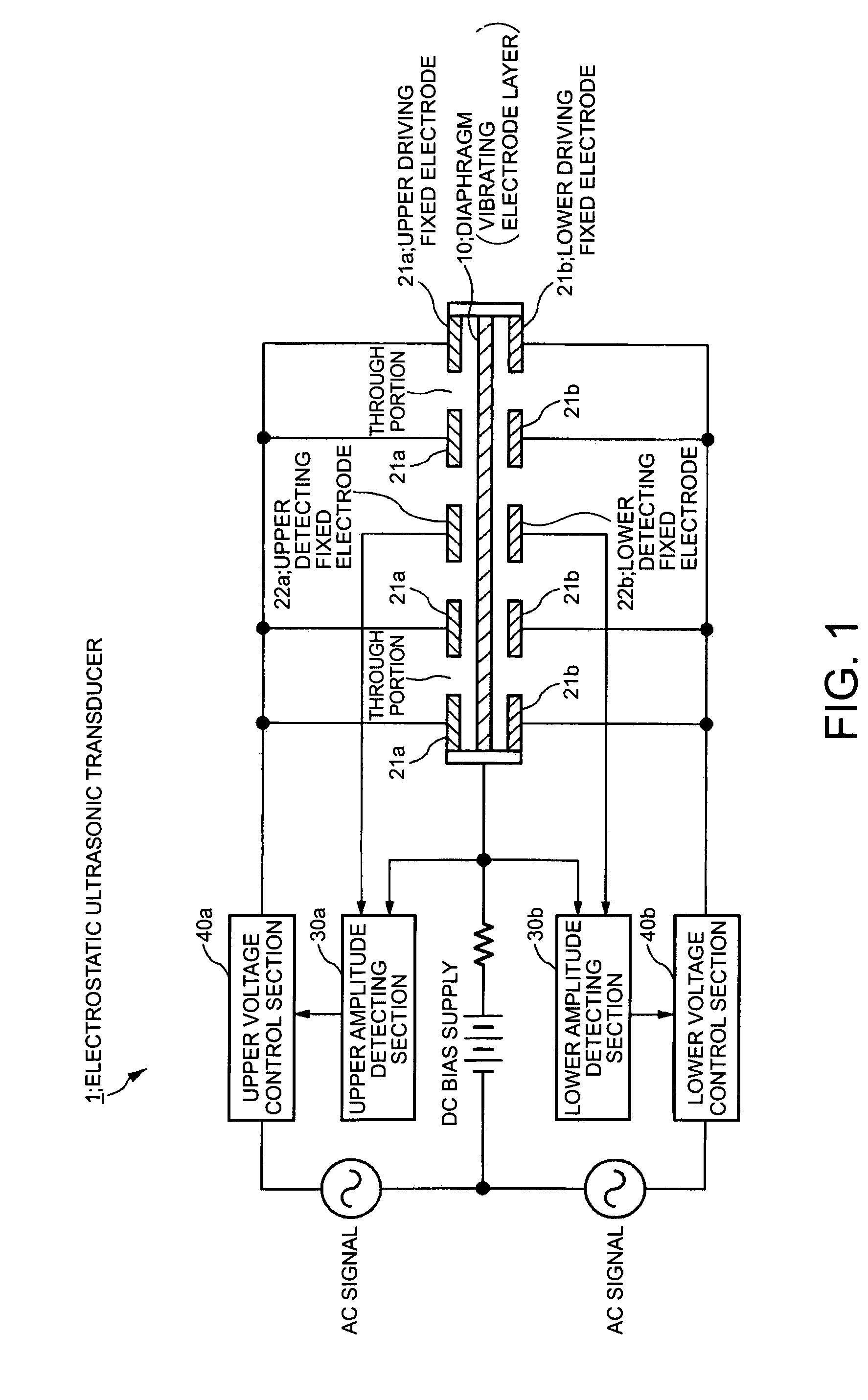
[0082]Structure of Ultrasonic Transducer of the Invention

[0083]FIG. 1 is a sectional view of a first structural example of an ultrasonic transducer of the invention. The ultrasonic transducer 1 shown in FIG. 1 is a push-pull electrostatic ultrasonic transducer, in which a diaphragm (vibrating electrode layer) 10 having a conducting layer is sandwiched between upper fixed electrodes (upper driving fixed electrodes 21a and an upper detecting fixed electrode 22a) and lower fixed electrodes (lower driving fixed electrodes 21b and a lower detecting fixed electrode 22b). The upper fixed electrodes (first fixed electrodes) and the lower fixed electrodes (second fixed electrodes) are arranged so as to face both sides of the diaphragm 10. In the ultrasonic transducer 1 shown in FIG. 1, the fixed electrodes 21a and 22a and the fixed electrodes 21b and 22b are symmetric with respect to the...


PUM


Abstract

An electrostatic ultrasonic transducer includes a diaphragm having a conducting layer and a pair of first and second fixed electrodes opposed to the corresponding surfaces of the diaphragm, the pair of fixed electrodes having a plurality of through holes in corresponding positions, wherein a DC bias voltage is applied to the conducting layer of the diaphragm and an alternating current signal is applied between the first and second fixed electrodes to generate an ultrasonic wave. Part of the pair of fixed electrodes includes s driving fixed electrode for driving the ultrasonic transducer, and the other part includes a detecting fixed electrode for detecting the amplitude of the diaphragm. The ultrasonic transducer includes a control unit that controls the vibration of the diaphragm so that the amplitude is proportional to the input signal based on the amplitude of the diaphragm detected by the detecting fixed electrode.

Description

RELATED APPLICATIONS[0001]This application claims priority to Japanese Patent Application No. 2004-181066 filed Jun. 18, 2004 which is hereby expressly incorporated by reference herein in its entirety.BACKGROUND[0002]1. Technical Field[0003]The present invention relates to an ultrasonic transducer, an ultrasonic speaker, and a method of controlling the driving of the ultrasonic transducer, and in particular, it relates to an electrostatic ultrasonic transducer, an ultrasonic speaker, and a method of controlling the driving of the ultrasonic transducer capable of outputting sound waves in response to input signals with high fidelity.[0004]2. Related Art[0005]Typical ultrasonic transducers include a piezoelectric transducer and an electrostatic transducer. The piezoelectric transducer uses a piezoelectric element such as piezo as a vibrator and is a resonant transducer of the type that operates using its resonant frequency band. Thus, it has the characteristic of generating a high sou...

Claims


Application Information

Patent Timeline
Patent Type & Authority Patents(United States)
IPC IPC(8): H02N1/00A61B8/00H04R25/00B06B1/02
CPCB06B1/0292H02N1/006
Inventor MIYAZAKI, SHINICHIUETAKE, AKIHITO
Owner SEIKO EPSON CORP
Why Eureka
Try Eureka