Welding device

a technology of a welding device and a clamping plate, which is applied in the direction of mechanical control devices, process and machine control, instruments, etc., can solve the problems of the malfunction of the measuring interval sensor, and achieve the effect of preventing the precision of the application of ultrasonic vibration from lowering and high precision of the positional relationship

Active Publication Date: 2008-06-10
ZUIKO CORP
View PDF10 Cites 80 Cited by
  • Summary
  • Abstract
  • Description
  • Claims
  • Application Information

AI Technical Summary

Benefits of technology

[0008]An object of the present invention is to provide a welding device, which is capable of achieving a high precision of the positional relationship between a welded area and a cut portion, and is capable of preventing the precision of the application of ultrasonic vibrations from lowering due to the vibration from cutting.

Problems solved by technology

Whether the interval is varied or not, such a vibration by the cutter may cause a malfunction of the sensor for measuring the interval.

Method used


Image

  • Welding device
  • Welding device
  • Welding device

Examples


first embodiment

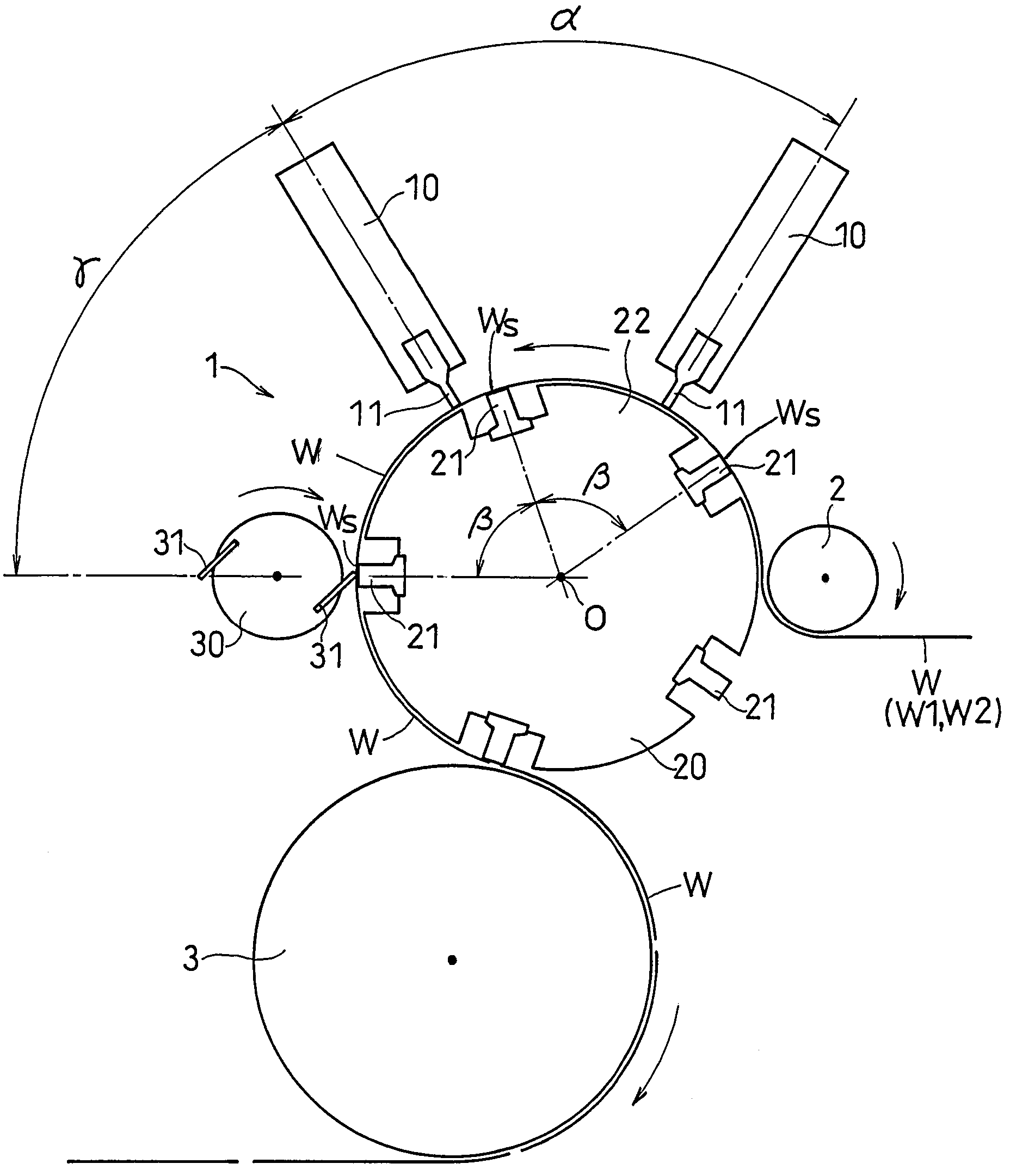
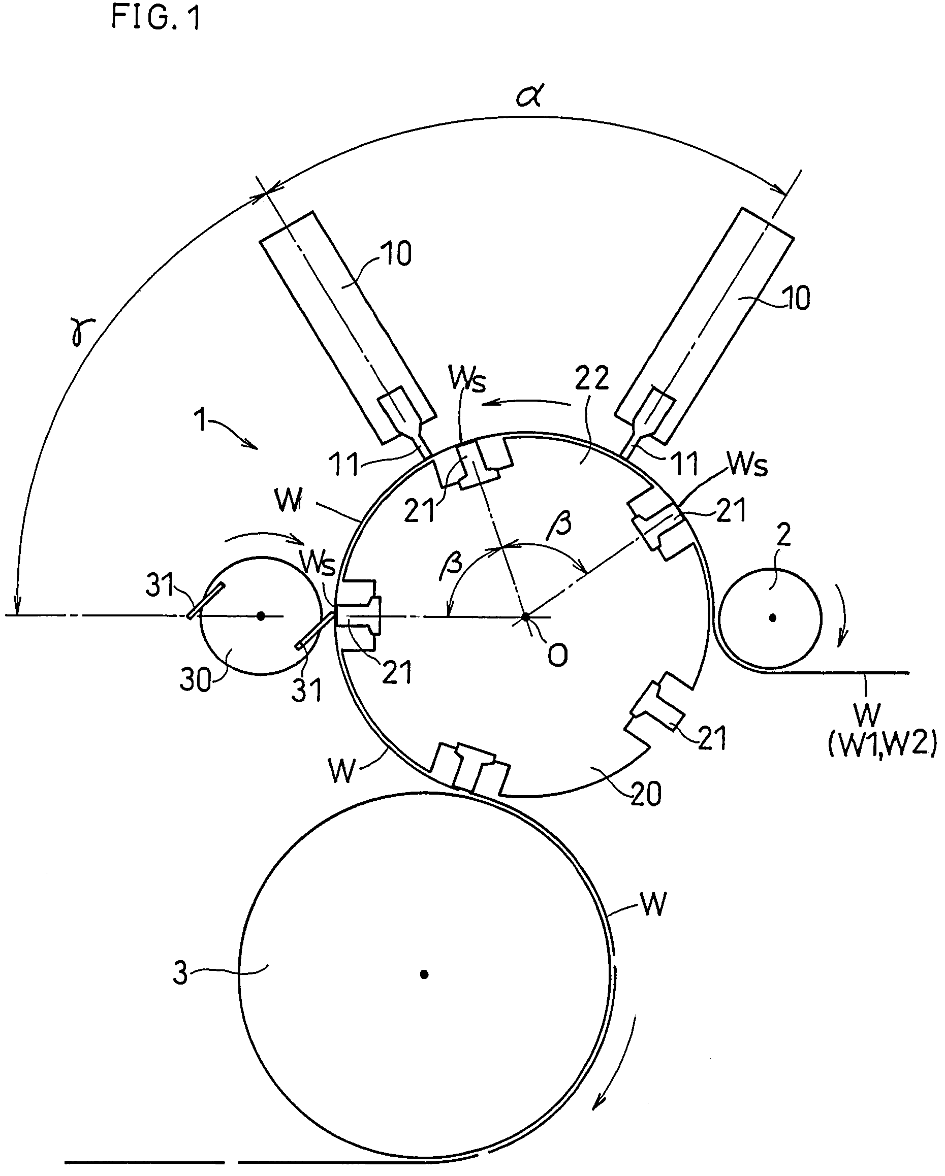
[0054]FIG. 1 shows the present invention.

[0055]As shown in FIG. 1, a welding device 1 transfers a continuous sheet-like material W and applies ultrasonic vibrations to a welding target portion Ws of the sheet-like material W, for example, as shown in FIG. 5(a), so as to thermally fuse the webs together at the welding target portion Ws, after which the welding device 1 cuts the sheet-like material W. For example, the sheet-like material W may be a semi-finished product. The sheet-like material W includes a first web W1 and a second web W2 laid on each other, and the webs are to be fused together at a predetermined welding target portion Ws in an area where the two webs W1 and W2 overlap with each other. For example, as shown in FIG. 5(b), webs of the semi-finished product W are welded (bonded) together in two welded areas, each being the welding target portion Ws, and then the semi-finished product W is cut along a cut line CL between the two welded areas Ws into individual articles ...


PUM

PropertyMeasurementUnit
vibration energyaaaaaaaaaa
distanceaaaaaaaaaa
ultrasonic vibrationsaaaaaaaaaa

Abstract

The present welding device is a device for welding webs W, the device including: a drum 20 and an anvil 21 rotating about an axis; a transfer section 22 provided on a periphery of the drum 20 to rotate together with the drum 20; a horn 11 which, together with the anvil 21, applies a vibration energy to a layered portion of the webs; a cutter 30 which comes into contact with the anvil 21 to cut the webs; a sensor 40 for measuring a distance between the anvil 21 and the horn 11; and a control section for controlling a relative positions of the anvil 21 and the horn 11 based on the measured distance between the anvil 21 and the horn 11 as measured by the sensor. While the horn 11, together with the anvil 21, applies the violation energy to the webs W, the cutting of the webs W by the cutter 30 is not performed.

Description

TECHNICAL FIELD[0001]The present invention relates to a welding device for welding a plurality of webs together by applying ultrasonic vibrations to the webs layered together into a sheet-like material.BACKGROUND ART[0002]In a packaging device of the first patent document identified below, a sealing device and a cutter are separate from each other. In this device, since the cutter and the sealer are separate from each other, a phase shift (displacement) occurs therebetween, lowering the precision of the positional relationship between a sealed area and a cut portion.[0003]In the fusing device of the second patent document identified below, a disc-shaped ultrasonic horn and a cutter are provided around a single drum. Therefore, fusion cannot be done in a direction along the rotation axis of the drum. Moreover, the second patent document fails to disclose performing the welding by ultrasonic vibrations and the cutting by a cutter at staggered times.[0004]In the fusing device of the th...

Claims


Application Information

Patent Timeline
Patent Type & Authority Patents(United States)
IPC IPC(8): G05G15/00B32B37/00A61F13/15A61F13/49B29C65/08
CPCA61F13/15739B29C65/086B29C66/21B29C66/961B29C66/81431B29C66/0326B29C66/1122B29C66/232B29C66/433B29C66/81433B29C66/81465B29C66/92311B29C66/92613B29C66/83511B29C66/9513B29L2031/4878Y10T156/12B29C66/431B29C66/73921
Inventor UMEBAYASHI, TOYOSHIYONEOKA, KIKUO
Owner ZUIKO CORP
Why Eureka
Try Eureka