Trochoidal oil pump

a technology of trochoidal oil and oil pump, which is applied in the direction of machines/engines, liquid fuel engines, positive displacement liquid engines, etc., can solve the problems of difficult to increase the pump efficiency, difficult to ensure a sufficient size of sealing parts and rectilinear parts, and top parts, so as to reduce noise, reduce discharge pulsation, and facilitate engagement

Active Publication Date: 2008-06-10
YAMADA SEISAKUSHO KK
View PDF23 Cites 7 Cited by
  • Summary
  • Abstract
  • Description
  • Claims
  • Application Information

AI Technical Summary

Benefits of technology

[0017]In the invention of claim 1, a reduction in discharge pulsation and a reduction in noise can be achieved since the plurality of inter-tooth spaces constructed by the outer rotor and inner rotor are placed in a state of communication in the formation regions of the intake port and discharge port. The adjacent inter-tooth spaces can ensure favorable engagement, and can stabilize the rotational driving of the rotors. Furthermore, since the fluid filling rate of the maximum sealed space can be increased, cavitation can be suppressed, and the pump efficiency can be improved. In the invention of claim 2, the pump has merits comparable to those of claim 1.
[0018]In the invention of claim 3, a favorable number of teeth can be obtained by setting the number of teeth of the inner rotor at 6 or greater; furthermore, since the tooth shape is a relatively large tooth shape in the outer rotor, non-contact regions can easily be formed. Moreover, in the invention of claim 4, the pump performance can be improved even further by forming the shape of the outer circumferential edge in the non-contact region of the tooth shape as a curved shape. Furthermore, in the invention of claim 5, a reduction in discharge pulsation and a reduction in noise can be achieved; furthermore, a drop in the discharge amount in the high-speed rotation region can be prevented, and the filling rate of the maximum sealed space can be increased. Accordingly, cavitation can be suppressed so that the pump efficiency can be improved.
[0019]In the invention of claim 6, the space of the communicating parts is increased even further, so that the amount of fluid flowing through the inter-tooth spaces is increased; accordingly, the flow rate is increased, and noise can be reduced. In the invention of claim 7, the width of the communicating parts that communicate between the inter-tooth spaces formed by the inner rotor and outer rotor on the intake port side in particular is broadened, so that the pressure balance of the fluid can be improved and the intake efficiency can be improved. In the invention of claim 8, the communicating parts between the inter-tooth spaces in the intake port and discharge port are widened by the formation of the recessed parts on both side surfaces of the tooth shape in the lateral direction; accordingly, the area of the inter-tooth spaces can be increased, so that the through-flow of the fluid can be improved, and the pump efficiency can be improved.
[0020]In the invention of claim 9, the fluid flowing through the communicating parts can flow extremely smoothly as a result of the formation of the recessed parts in a flattened arc shape. Next, in the invention of claim 10, since the shapes of the recessed parts on both sides of the tooth shape of the outer rotor in the lateral direction are formed as symmetrical shapes, dimensional variation in the manufacturing process can be reduced, so that the precision of the tooth shape of the outer rotor can be improved. In the invention of claim 11, the width of the communicating parts between the inter-tooth spaces on the intake port side is broadened, so that the pressure balance of the fluid is improved. Accordingly, a reduction in discharge pulsation and a reduction in noise can be achieved; furthermore, a drop in the discharge amount in the high-speed rotation region can be prevented, cavitation can be suppressed, and erosion can be reduced.

Problems solved by technology

Consequently, when the volume space between the rotors in the partition part is at a maximum, this volume space communicates with the intake port in a state in which the volume space is not closed off; accordingly, the back flow of the fluid inside the volume space to the intake port cannot be prevented, so that it is difficult to increase the pump efficiency.
Next, in Japanese Patent Publication No. 5-1397, since sealing parts (P1) that contact the inward-facing engaging teeth of the driven gear, and non-contact rectilinear parts (30b, 30c), are formed in locations on the top parts of the outward-facing engaging teeth of the drive gear, it is actually extremely difficult to ensure a sufficient size of the sealing parts and size of the rectilinear parts in the limited range of these top parts; as a result, the rectilinear parts have an extremely limited small range.
The formation of communicating passages that communicate between the adjacent volume spaces that are formed between the drive gear and driven gear by the rectilinear parts formed on the outward-facing engaging teeth is limited to an extremely small range; in actuality, therefore, the non-contact parts have an extremely small range, and it is difficult to vary the size range of these communicating passages or to ensure a sufficiently large size.
Consequently, it is difficult to prevent the generation of noise.
Consequently, in cases where non-contact parts are formed on the outward-facing engaging teeth, if a sufficiently large size is ensured for the engaging parts, the non-contact parts have an extremely small range, so that it is difficult to cause these parts to play the role of communicating passages.
Conversely, if the size of the non-contact parts is increased in an attempt to ensure communicating passages, the engaging parts are not sufficiently ensured, so that it becomes difficult to stabilize the rotational driving of the rotors.
Thus, it is extremely difficult to simultaneously satisfy the requirements for both communicating passages and engagement, and the communicating passages can be installed in only an extremely limited range.
Accordingly, even if the engaging parts are ensured, the communicating passages are narrow and the flow rate is small, so that it is difficult to suppress pump noise to a low level, and to reduce discharge pulsation.

Method used


Image

  • Trochoidal oil pump
  • Trochoidal oil pump
  • Trochoidal oil pump

Examples


Embodiment Construction

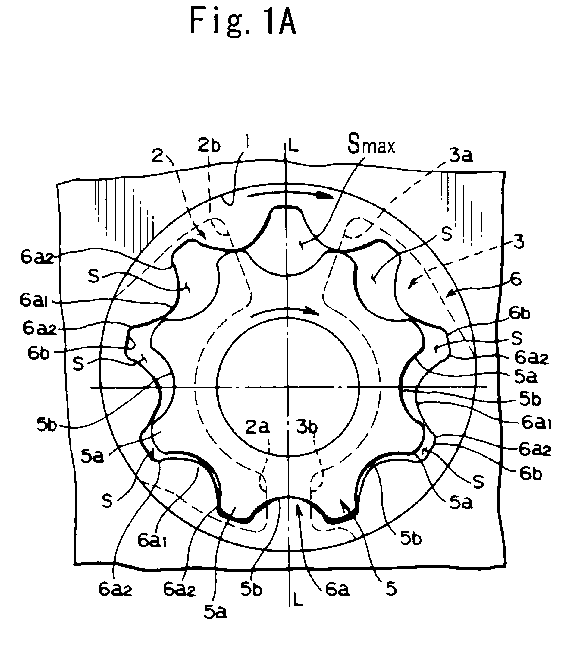
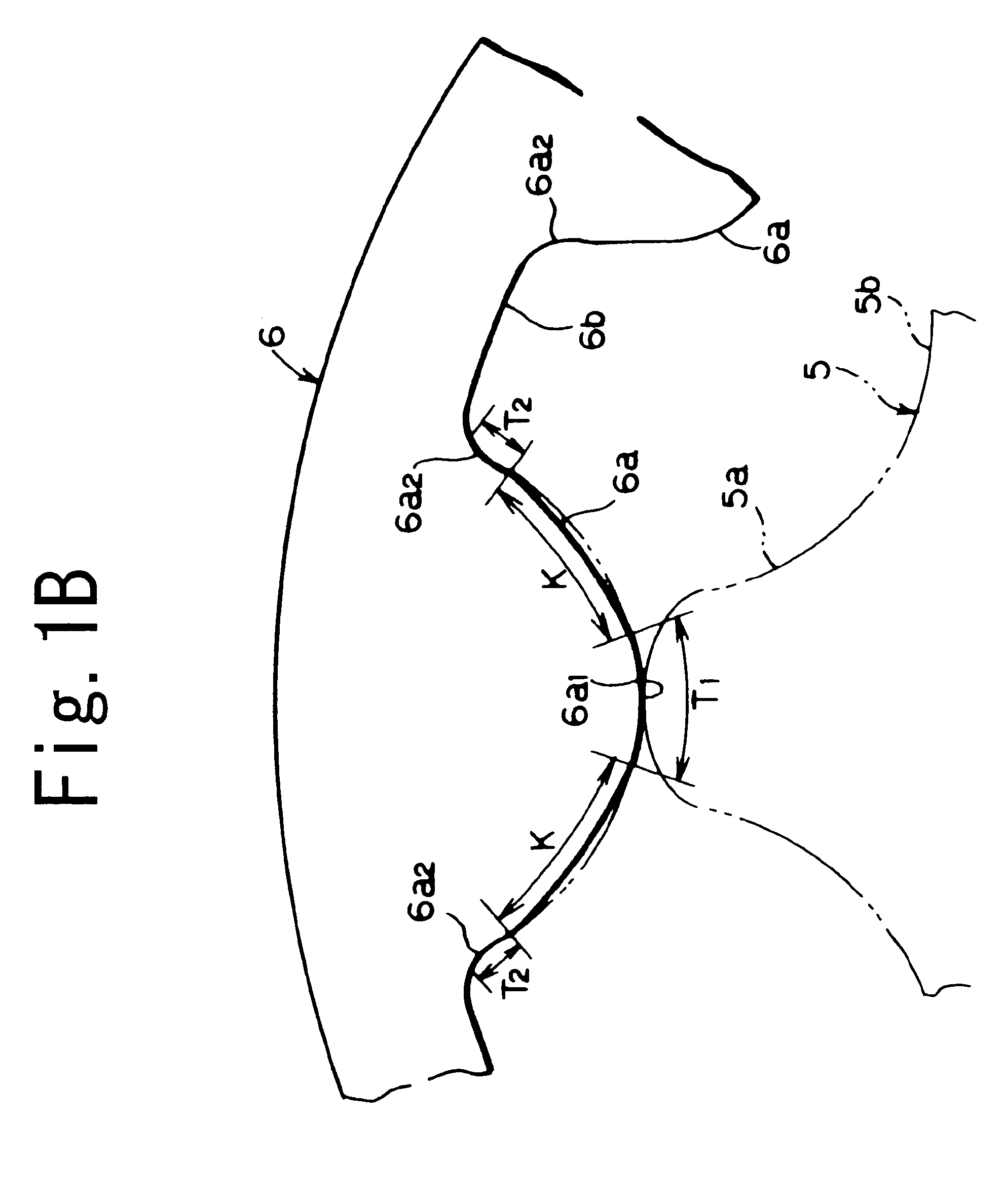
[0045]Preferred embodiments of the present invention will be described below with reference to the attached figures. As is shown in FIG. 1A, the trochoidal oil pump of the present invention is a pump in which an inner rotor 5 and outer rotor 6 with a trochoidal tooth shape are mounted in a rotor chamber 1 formed inside a pump casing. As is shown in FIG. 7A, an intake port 2 and a discharge port 3 are formed substantially on the side of the outer circumference along the circumferential direction in the rotor chamber 1. The intake port 2 and discharge port 3 are formed in positions that show left-right symmetry with respect to the center of the rotor chamber 1. In concrete terms, as is shown in FIG. 1A, FIG. 7A and the like, if a perpendicular line that passes through the center of the rotor chamber 1 with respect to the lateral direction is taken as a virtual left-right symmetry line L, then the intake port 2 is formed so that this port is disposed on the left side of the left-right ...


PUM


Abstract

A trochoidal oil pump which makes it possible to achieve an improved reduction in discharge pulsation and noise, and which makes it possible to realize such a reduction using an extremely simple structure. The trochoidal oil pump of the present invention comprises a rotor chamber 1 which has an intake port 2 and discharge port 3, an outer rotor 6 and an inner rotor 5. A plurality of inter-tooth spaces S, S, . . . that are formed by the tooth shapes 5a and 6a of the inner rotor 5 and outer rotor 6 comprise a maximum sealed space Smax that is positioned in the region of the partition part 4 between the intake port 2 and discharge port 3, a plurality of inter-tooth spaces S, S, . . . within the region of the intake port 2, and a plurality of inter-tooth spaces S, S, . . . within the region of the discharge port 3. The plurality of inter-tooth spaces S, S, . . . in the intake port 2 and discharge port 3 respectively communicate with each other

Description

BACKGROUND OF THE INVENTION[0001]1. Field of the Invention[0002]The present invention relates to a trochoidal oil pump which makes it possible to improve the reduction of discharge vibration and noise, and which makes it possible to realize this improvement by means of an extremely simple structure.[0003]2. Description of the Related Art[0004]A pump with a construction in which the addendum part and deddendum part of the inner rotor are formed by circular arcs, the addendum part and deddendum part of the outer rotor are formed by circular arcs that correspond to the circular arc tooth shape of said inner rotor, and the deddendum part of the outer rotor is formed with dimensions that are the same as or greater than the dimensions of the addendum part of said outer rotor, so that the space between the inner rotor and outer rotor is divided into only two spaces, i.e., a space that communicates with the intake port and a space that communicates with the discharge port, is disclosed in J...

Claims


Application Information

Patent Timeline
Patent Type & Authority Patents(United States)
IPC IPC(8): F01C1/02F04C2/08F04C15/00F04C2/10
CPCF04C2/084F04C15/0049F04C2/102
Inventor FUJIKI, KENICHIAMANO, MASARU
Owner YAMADA SEISAKUSHO KK
Why Eureka
Try Eureka