Rapid prototyping system with controlled material feedstock

a technology of material feedstock and rapid prototyping, which is applied in the direction of additive manufacturing processes, dough shaping, manufacturing tools, etc., can solve the problems of inability to build three-dimensional models that may not be as structurally sound, the filament slippage of the feed roller, and the shortage of modeling materials

Active Publication Date: 2008-06-10
STRATSYS INC
View PDF67 Cites 253 Cited by
  • Summary
  • Abstract
  • Description
  • Claims
  • Application Information

AI Technical Summary

Benefits of technology

[0013]The invention relates to a deposition modeling system that utilizes a drive mechanism to feed a strand of filament to create a model. The drive mechanism comprises a pivot block that is rotatably connected to a fixed block and a motor that rotates a drive shaft. A drive roller is connected to the drive shaft and an idler roller is connected to an idler axle that extends from the pivot block in a substantially perpendicular direction to the direction of rotation of the pivot block with respect to the fixed block and a parallel direction to the drive shaft. The drive roller further includes a channel around its outer circumferential surface that includes a series of teeth to drive the strand of filament.

Problems solved by technology

Slippage of the filament in the feed rollers occurs when the filament fails to advance at the desired rate despite rotation of the feed rollers.
Filament slippage creates a shortage of modeling material that is supplied to the extrusion head that in turn creates a shortage of modeling material to build the desired three-dimensional model at the defined time and location.
This can result in an unsuccessful build of the three-dimensional model that may not be as structurally sound as the designed part or may be deformed due to the shortage of modeling material during the building process.
However, time and varying diameters of strands of filament driven by the feed rollers cause wear on the urethane feed rollers which ultimately lead to an inability of the feed rollers to apply sufficient compression on the strand of filament for consistent advancement under varying conditions.
In particular, as the required push force to advance the filament approaches twenty pounds of pressure, it often exceeds the amount of force that urethane feed rollers are able to apply to the filament resulting in the filament slipping and not advancing at the desired rate if even at all.

Method used


Image

  • Rapid prototyping system with controlled material feedstock
  • Rapid prototyping system with controlled material feedstock
  • Rapid prototyping system with controlled material feedstock

Examples


Embodiment Construction

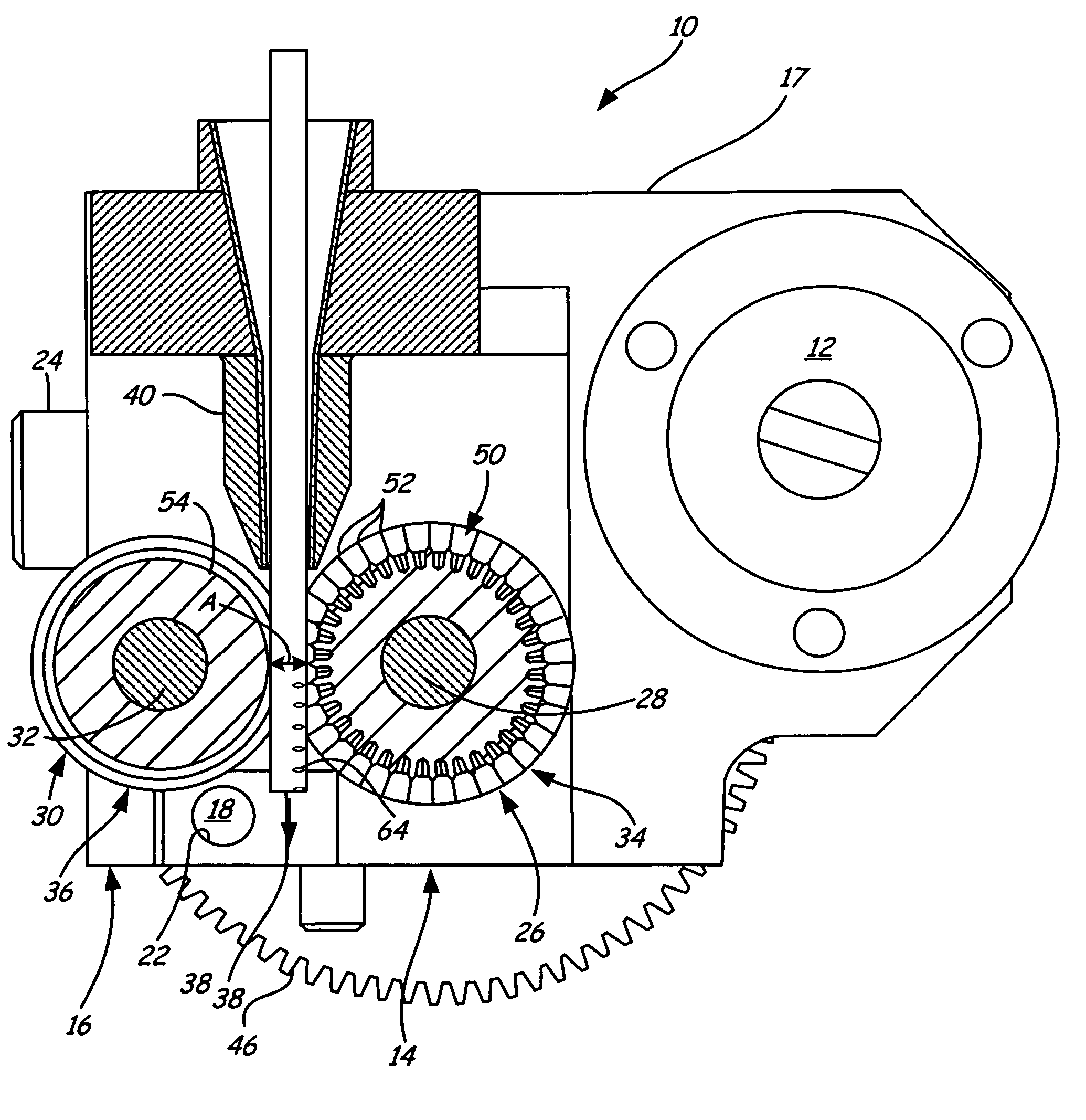
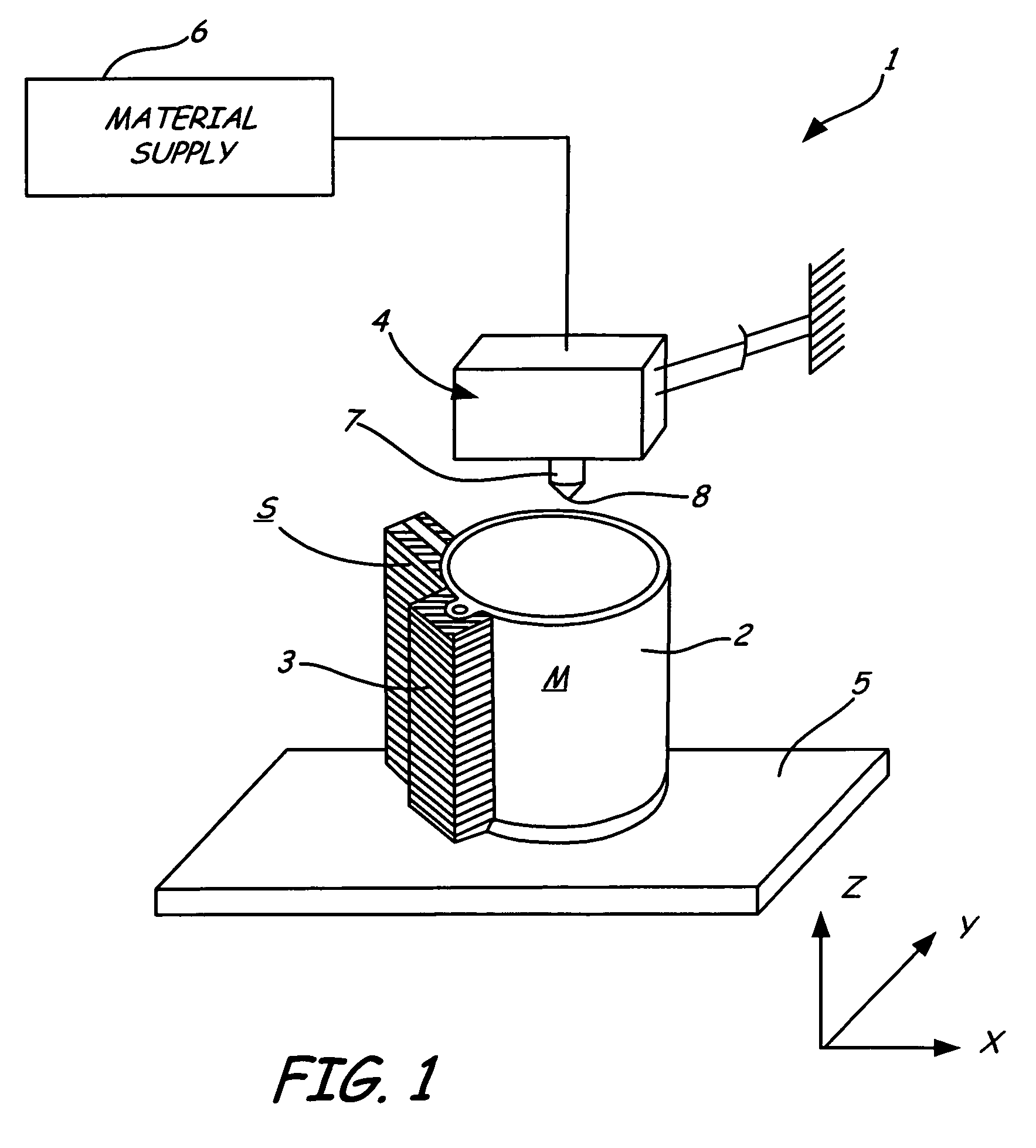
[0026]The present invention is described with reference to a deposition modeling system of the type shown in FIG. 1. FIG. 1 shows an extrusion apparatus 1 building a model 2 supported by a support structure 3 according to the present invention. The extrusion apparatus 1 includes an extrusion head 4, a material-receiving base 5 and a material supply 6. The extrusion head 4 moves in X and Y directions with respect to the base 5, which moves in a vertical Z direction. The material supply 6 supplies a feedstock of material to the extrusion head 4. In the described embodiment, a solid feedstock of material is supplied to the extrusion head 4, and is melted in a liquifier 7 carried by the extrusion head 4. The liquifier 7 heats the feedstock material to a temperature slightly above its solidification point, reducing it to a molten state. Molten material is extruded through a nozzle 8 of the liquifier 7 onto the base 5.

[0027]The movement of the extrusion head 4 is controlled so as to depos...


PUM

PropertyMeasurementUnit
angleaaaaaaaaaa
angleaaaaaaaaaa
widthaaaaaaaaaa

Abstract

A deposition modeling system incorporates a drive mechanism to feed a strand of filament to create a model. The drive mechanism comprises a pivot block that is rotatably connected to a fixed block and a motor that rotates a drive shaft. A drive roller is connected to the drive shaft and an idler roller is connected to an idler axle that extends from the pivot block in a substantially perpendicular direction to the direction of rotation of the pivot block with respect to the fixed block and in a substantially parallel direction to the drive shaft.

Description

CROSS-REFERENCE TO RELATED APPLICATION(S)[0001]None.BACKGROUND OF THE INVENTION[0002]This invention relates to the fabrication of three-dimensional objects using extrusion-based layered manufacturing techniques. More particularly, the invention relates to a deposition modeling system utilizing a feed drive mechanism that accommodates filament having various diameters, more effectively controls movement of the filament and is easier to service and repair.[0003]Three-dimensional models are used for functions including aesthetic judgments, proofing a mathematical computer aided design (CAD) model, forming hard tooling, studying interference and space allocation, and testing functionality. Extrusion-based layered manufacturing machines build up three-dimensional models by extruding solidifiable modeling material from an extrusion head in a predetermined pattern, based upon design data provided from a CAD system. A feedstock of either a liquid or solid modeling material is supplied to th...

Claims


Application Information

Patent Timeline
Patent Type & Authority Patents(United States)
IPC IPC(8): A21C3/00B28B17/00
CPCB29C67/0055B29C64/118B29C64/227B29C48/865B29C48/02B29C48/05B29C48/2528B29C48/266B33Y30/00B29C64/106
Inventor LABOSSIERE, JOSEPH EDWARDESHELMAN, MARVIN E.
Owner STRATSYS INC
Why Eureka
Try Eureka