
Method and apparatus for manufacturing and constructing a physical dental arch model

a dental arch and model technology, applied in the field of dental care, can solve the problems of manual application of such bends, humanly impossible to accurately estimate three-dimensional wire bends, and inability to accurately develop a visual three-dimensional image of an orthodontic structure, etc., to achieve the effect of reducing waste and cycle times, simple manufacturing, and convenient us

Active Publication Date: 2008-06-10
ALIGN TECH
View PDF53 Cites 43 Cited by
  • Summary
  • Abstract
  • Description
  • Claims
  • Application Information

AI Technical Summary

Benefits of technology

This approach simplifies the production of accurate dental arch models, reduces waste and cycle times, and allows for the practical manufacture of complex shapes, enhancing the efficiency and consistency of orthodontic treatments.

Problems solved by technology

Unfortunately, in the oral environment, it is impossible for a human being to accurately develop a visual three-dimensional image of an orthodontic structure due to the limitations of human sight and the physical structure of a human mouth.
In addition, it is humanly impossible to accurately estimate three-dimensional wire bends (with an accuracy within a few degrees) and to manually apply such bends to a wire.
Further, it is humanly impossible to determine an ideal bracket location to achieve the desired orthodontic structure based on the mental images.
It is also extremely difficult to manually place brackets in what is estimated to be the ideal location.
As a result of multiple wire changes, patient discomfort is increased as well as the cost.
That is, when an appliance is first worn by the patient, certain of the teeth will be misaligned relative to an undeformed geometry of the appliance cavity.
Making a model for a whole or a large portion of an dental arch is much more difficult than making one tooth abutment for implant purposes.
Some prior art making the physical dental arch model is carried out manually, involving not only a substantial amount of labor required, but also a substantial amount of time.
It is also extremely difficult to machine an accurate dental arch model because of the various complex shapes and the complex features such as inter-proximal areas, wedges between teeth, etc. in a dental arch.

Method used


Image

  • Method and apparatus for manufacturing and constructing a physical dental arch model
  • Method and apparatus for manufacturing and constructing a physical dental arch model
  • Method and apparatus for manufacturing and constructing a physical dental arch model

Examples


Embodiment Construction

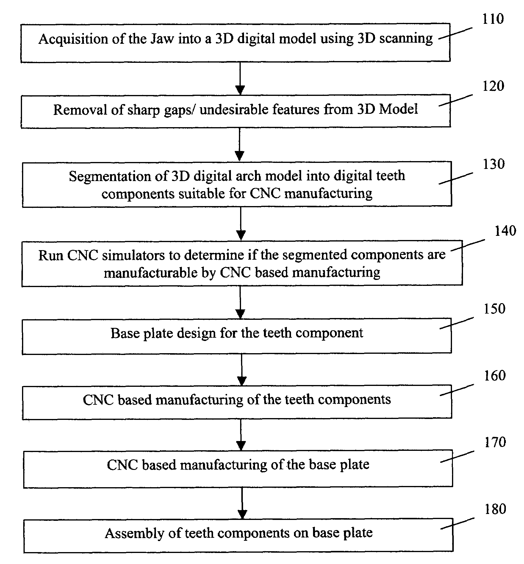
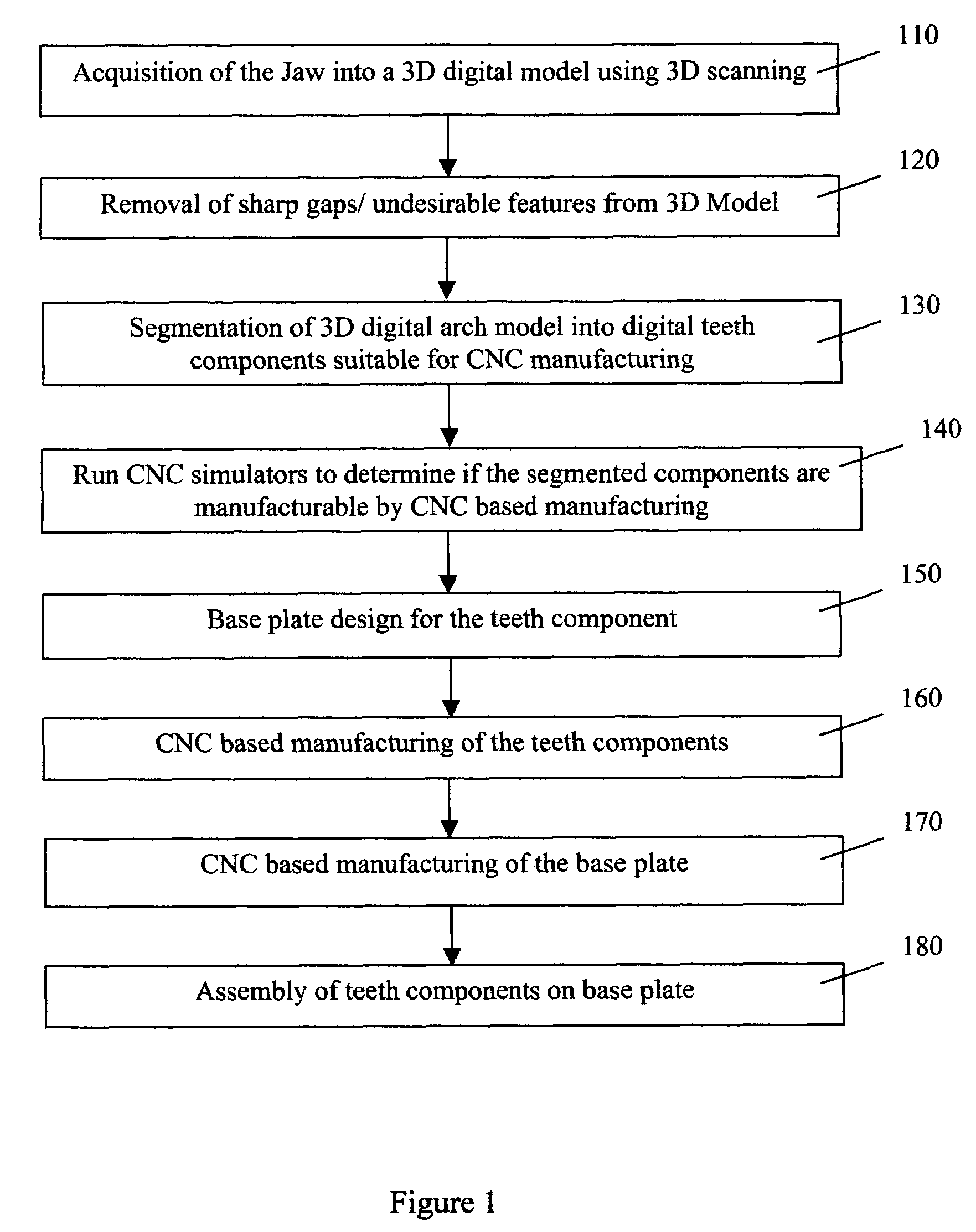
[0051]A flow chart shown in FIG. 1 illustrates the key steps of producing a physical dental archphysical dental arch model in accordance with the present invention. First, a digital model is acquired from a patient's arch in step 110. The digital model is three dimensional and can be obtained by 3D scanning of a cast produced from the patient's arch. The digital model includes a mesh of points in three dimensions that define the surfaces of an entire or a large portion of an upper or lower arch. Details of obtaining a digital model of an arch are disclosed in above referenced and currently filed U.S. patent application Ser. No. titled “Producing a base for a physical dental archphysical dental arch model” by Huafeng Wen, the content of which is incorporated herein by reference.

[0052]Next, in step 120, the digital dental arch model is smoothened by computer processing. A software takes the digital dental arch model as input. One or more criteria for the degree of smoothness can also ...


PUM


Abstract

A method produces a physical dental arch model based on a three-dimensional (3D) digital dental arch model. The method includes smoothening the digital dental arch model to make the digital dental arch model suitable for CNC based manufacturing, segmenting the digital dental arch model into at least two manufacturable digital components, producing manufacturable physical components using Computer Numerical Control (CNC) based manufacturing in accordance with the manufacturable digital components, and assembling the manufacturable physical components to form the physical dental arch model.

Description

TECHNICAL FIELD[0001]This application generally relates to the field of dental care, and more particularly to a system and a method for manufacturing and constructing a physical dental arch model.CROSS-REFERENCES TO RELATED INVENTIONS[0002]The present invention is related to concurrently filed U.S. Patent Application, titled “Method and apparatus for manufacturing and constructing a dental aligner” by Huafeng Wen, concurrently filed a U.S. Patent Application, titled “Producing an adjustable physical dental arch model” by Huafeng Wen, and concurrently filed U.S. Patent Application, titled “Producing a base for a physical dental arch model” by Huafeng Wen. The disclosure of these related applications are incorporated herein by reference.BACKGROUND[0003]Orthodontics is the practice of manipulating a patient's teeth to provide better function and appearance. In general, brackets are bonded to a patient's teeth and coupled together with an arched wire. The combination of the brackets and...

Claims


Application Information

Patent Timeline
Patent Type & Authority Patents(United States)
IPC IPC(8): A61C11/00
CPCA61C9/002A61C13/0004B33Y50/00B33Y80/00
Inventor WEN, HUAFENG
Owner ALIGN TECH
Learn More