RF connector with adjacent shielded modules

a shielded module and connector technology, applied in the direction of coupling device details, coupling device connections, contact members penetrating/cutting insulation/cable strands, etc., can solve the problem that current connection strategies may not meet the requirements of centerline-to-centerline communication devices to antenna spacing in the near future, and achieve the effect of ensuring electrical connectivity

Active Publication Date: 2008-06-10
TYCO ELECTRONICS LOGISTICS AG (CH)
View PDF9 Cites 25 Cited by
  • Summary
  • Abstract
  • Description
  • Claims
  • Application Information

AI Technical Summary

Problems solved by technology

However, with the ongoing trends for miniaturization and space conservation in electronic systems, it may be anticipated that current connection strategies may not meet the centerline-to-centerline communication device to antenna spacing requirements in the near future.

Method used


Image

  • RF connector with adjacent shielded modules
  • RF connector with adjacent shielded modules
  • RF connector with adjacent shielded modules

Examples


Embodiment Construction

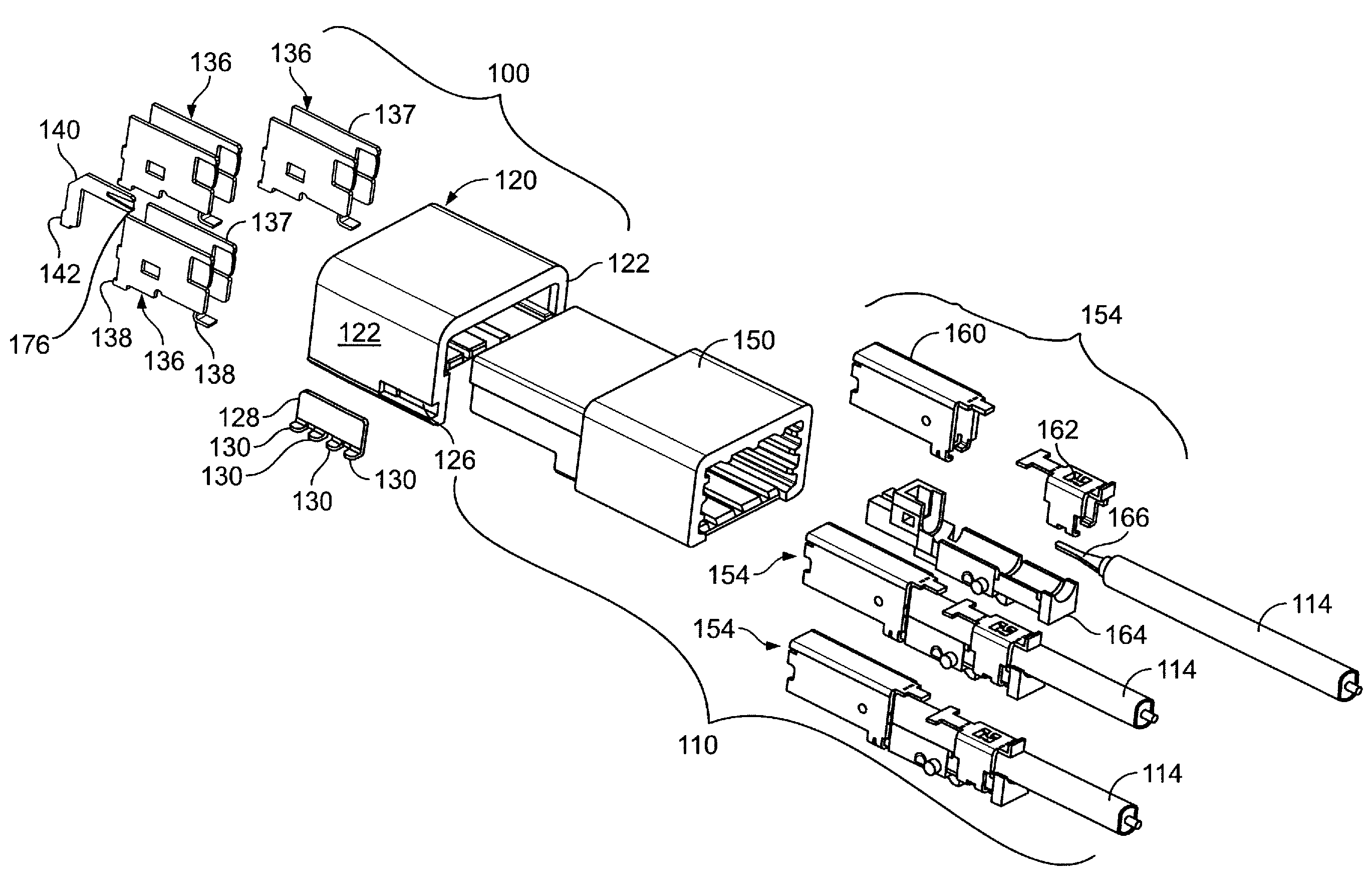
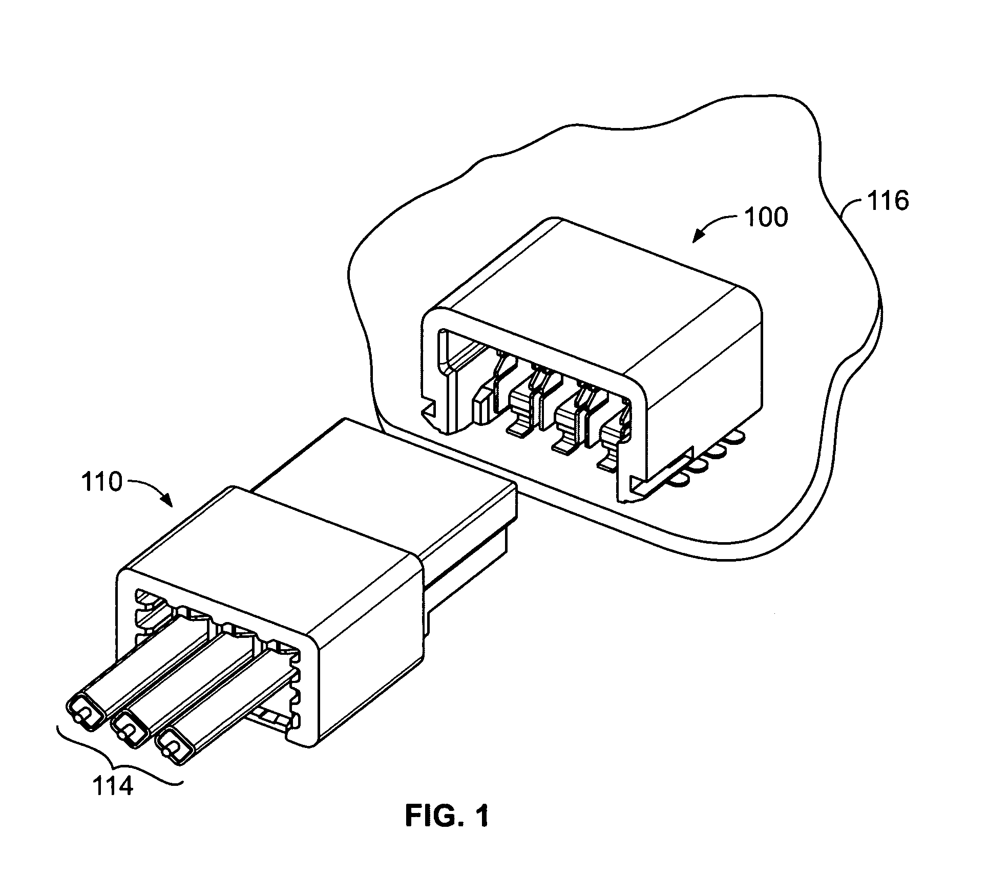
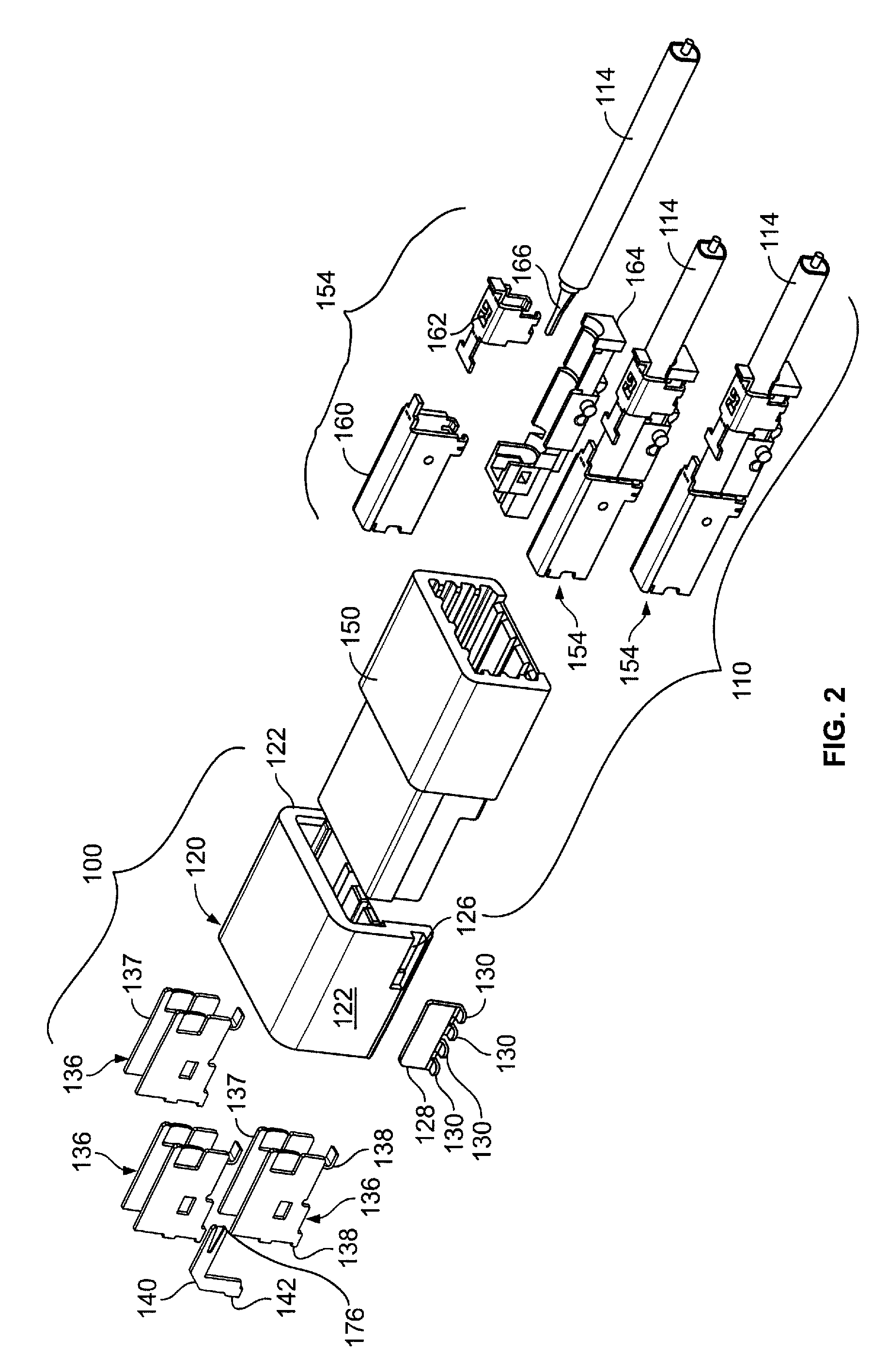
[0018]FIG. 1 is a perspective view of a receptacle connector assembly 100 and a mating plug connector assembly 110 formed in accordance with an exemplary embodiment of the present invention. As shown in FIG. 1, the receptacle and plug assemblies 100 and 110 are formed as a three-circuit connector assembly. Each circuit is associated with one of three coaxial cables 114 terminated to the plug assembly 110. It is to be understood however, that the configuration shown is for example only and no limitation is intended thereby. The receptacle and plug assemblies 100, 110 may be fabricated to provide any number of connections in the side by side arrangement shown. Similarly, the receptacle assembly 100 though illustrated as a board mount receptacle assembly attached to a circuit board 116, may also be used in a cable-to-cable or wire-to-wire design. The circuits may carry RF signals. The receptacle and plug assemblies 100, 110 provide a minimized centerline spacing between adjacent connec...


PUM


Abstract

An electrical connector includes a shield having opposed planar side panels. The shield is configured to receive a shield of a mating connector within the side panels. A dielectric is attached to the shield. The dielectric is configured to receive the coaxial cable and the shield is electrically connected to an outer conductor of the coaxial cable. The side panels are configured to abut and engage side panels of an adjacent connector with a substantially flush fit to form a row of connectors to be located in an outer housing. A separate strain relief member may be attached to the shield. Each of the shield and the strain relief member may include an IDC feature that pierces the cable insulation.

Description

BACKGROUND OF THE INVENTION[0001]The invention relates generally to coaxial cable connectors, and more particularly to a coaxial cable connector assembly suitable for use in multi-connector RF assemblies.[0002]Generally, coaxial cables have a circular geometry formed with a central conductor (of one or more conductive wires) surrounded by a cable dielectric material. The dielectric material is surrounded by a cable braid (of one or more conductive wires) that serves as a ground, and the cable braid is surrounded by a cable jacket. In most coaxial cable applications, it is preferable to match the impedance between source and destination electrical components located at opposite ends of the coaxial cable. Consequently, when sections of coaxial cable are interconnected by connector assemblies, it is preferable that the impedance remain matched through the interconnection.[0003]Today, coaxial cables are widely used. Recently, demand has risen for radio frequency (RF) coaxial cables in a...

Claims


Application Information

Patent Timeline
Patent Type & Authority Patents(United States)
IPC IPC(8): H01R9/05
CPCH01R13/65807H01R24/50H01R13/6597H01R13/6585H01R13/6592H01R2103/00
Inventor MALSTROM, CHARLES RANDALLMCCARTHY, SEAN PATRICKSPITLER, ALEXANDRA LYNNE MATTHEWSCONSOLI, JOHN JOSEPH
Owner TYCO ELECTRONICS LOGISTICS AG (CH)
Why Eureka
Try Eureka