
Manually controlled skimming of industrial oil contaminants

a technology of industrial oil contaminants and skimming, which is applied in water cleaning, multi-stage water/sewage treatment, separation processes, etc., can solve the problems of contaminating the washing solution with manufacturing oils and heat treating quench oils, adding time and expense, and endangering the health and safety of the workers of the plant, so as to achieve convenient and advantageous use and easy deployment

Inactive Publication Date: 2008-06-10
TERRIEN RICHARD J +1
View PDF109 Cites 9 Cited by
  • Summary
  • Abstract
  • Description
  • Claims
  • Application Information

AI Technical Summary

Benefits of technology

Enables efficient and safe removal of oil contaminants from small volumes and tanks with obstacles, improving operational efficiency and reducing environmental and health hazards by allowing batch processing and easy deployment across multiple tanks.

Problems solved by technology

For example, many machine parts or heat treated parts are washed in parts washing tanks, resulting in the washing solution becoming contaminated with manufacturing oils and heat treating quench oils.
Oily contamination in the parts washing solutions contributes to an inefficient cleaning process which typically requires secondary cleaning and manufacturing steps to correct, which then result in added time and expense.
Moreover, the presence of the oily contaminant also endangers the health and safety of the plant workers.
Not only is the in-plant smoke a danger, but frequent changes of washing baths due to oil contamination require increased worker exposure to cleaning fluids and related handling hazards.
Thus, these systems are generally large, heavy, and relatively immobile as they are fixed in place, and then operated continuously.
However, there are many situation in which such large, immobile systems are less than ideal.
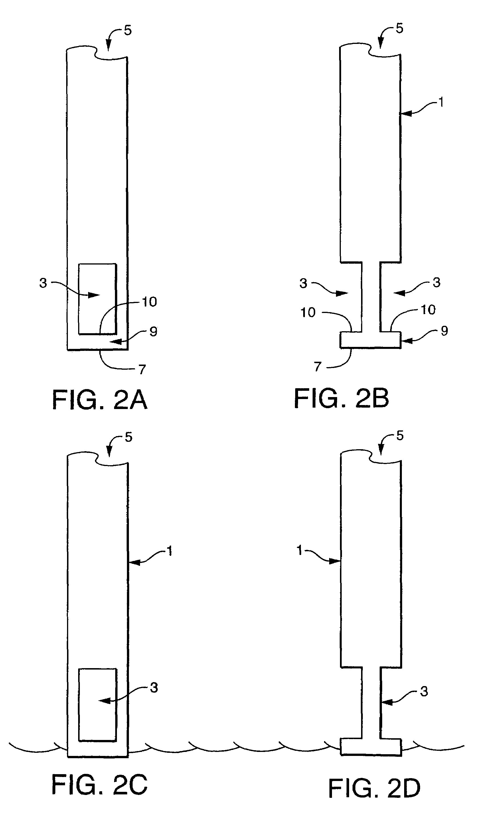
Such obstacles include mechanical apparatus supporting the tank's purpose, including sprann and immersion hardware.

Method used


Image

  • Manually controlled skimming of industrial oil contaminants
  • Manually controlled skimming of industrial oil contaminants
  • Manually controlled skimming of industrial oil contaminants

Examples


Embodiment Construction

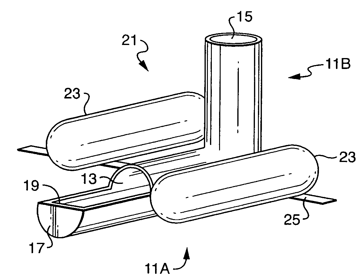
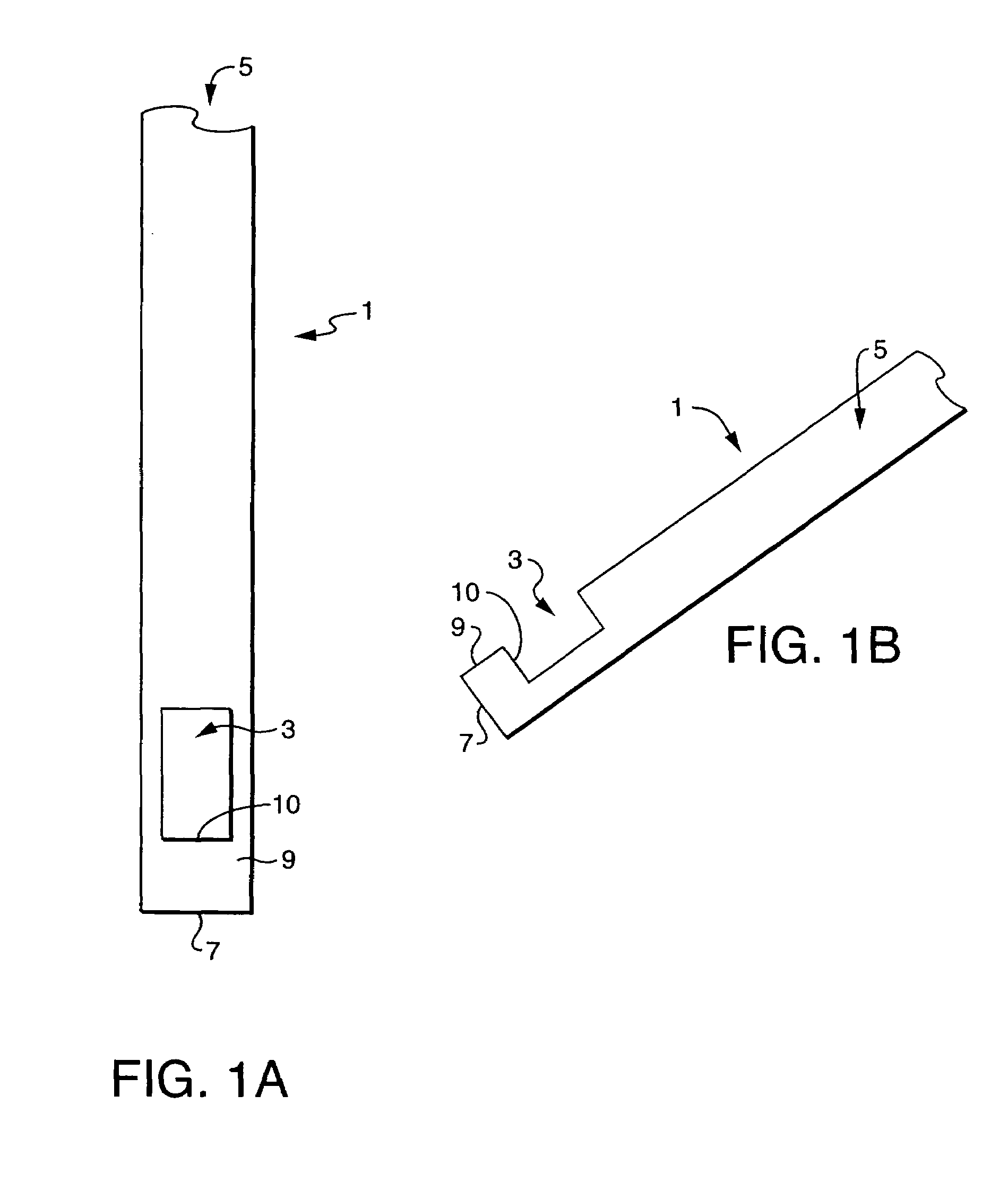
[0058]The present invention is directed to a method for removing a layer or a batch of an oil contaminant from the surface of solution, and to a system for carrying out the methods of the invention, where the system is small, easily used, and mobile. The small size and mobility of the system means that it is easily deployed, for example by a single operator, at the site of contamination, for example a tank containing an oil contaminated solution in an industrial setting, and that it can be easily moved, for example by a single operator, and from tank to tank in an industrial setting. The small size and mobility of the system, in which an operator manually operates the skimmer, allows for increased accuracy in removing an oil contaminant from small surfaces of solution; it also allows for removal of oil contaminants at locations in which access is limited by space or time constraints.

[0059]The system of the present invention for carrying out the methods of the invention comprises a s...


PUM

PropertyMeasurementUnit
angleaaaaaaaaaa
surface areaaaaaaaaaaa
volumesaaaaaaaaaa

Abstract

The present invention provides a method for removing an oil contaminant from a surface of an aqueous solution, comprising manually controlling a surface skimmer from a remote location to remove a layer or a batch of an oil contaminant from an oil-aqueous solution mixture by the skimmer, where the aqueous solution is contaminated by the oil as a result of an industrial process. The present invention also provides a system for carrying out the method, which comprises a surface skimmer, a collection means which is preferably a separator, a conduit connecting the skimmer to the collection means in an airtight fashion, and means for creating negative pressure in the skimmer, where the skimmer is capable of manual control from a remote location; in further embodiments, the system further comprises an air filtering means.

Description

[0001]This application is a continuation application of U.S. patent application Ser. No. 10 / 611,098, filed Jul. 1, 2003, issued Dec. 7, 2004 as U.S. Pat. No. 6,827,853, which claims priority to U.S. patent application Ser. No. 09 / 912,765, filed Mar. 20, 2001, issued Sep. 14, 2004 as U.S. Pat. No. 6,790,370, which claims priority to provisional patent application Ser. No. 60 / 393,282, filed Jul. 1, 2002, each of which is herein incorporated by reference in their entireties.FIELD OF THE INVENTION[0002]The present invention relates to removal and treatment of a surface layer of liquid which floats atop another liquid, and in particular to the removal and treatment of a surface layer of an oil or oil-like substance from a contained body of an aqueous solution.BACKGROUND OF THE INVENTION[0003]Oil-water mixtures are generated as a result of various activities, and a major source of such mixtures is industrial activity. For a number of reasons, it is desirable to separate the oil from such ...

Claims


Application Information

Patent Timeline
Patent Type & Authority Patents(United States)
IPC IPC(8): B01D29/00C02F1/40B01D17/02B01D19/02B01D21/00C02F1/68C02F9/00E02B15/10
CPCB01D17/0214B01D19/02B01D21/0012B01D21/2433C02F9/005C02F1/40C02F1/681C02F2103/16C02F2201/008C02F2301/063Y10S210/923C02F9/20
Inventor TERRIEN, RICHARD J.WALKER, DAVID T.
Owner TERRIEN RICHARD J
Learn More