Cogging reduction in permanent magnet machines

a permanent magnet machine and cogging technology, applied in the field of electric machines, can solve the problems of reducing the efficiency of the motor, affecting the drive load, adding maintenance costs to the motor, bearings and related equipment, etc., and achieve the effect of reducing the cogging torqu

Active Publication Date: 2008-06-10
BALDOR ELECTRIC COMPANY
View PDF225 Cites 41 Cited by
  • Summary
  • Abstract
  • Description
  • Claims
  • Application Information

AI Technical Summary

Benefits of technology

[0008]In another aspect, the invention provides a permanent magnet motor including a rotor having a plurality of permanent magnets defining a plurality of poles, each pole having a leading edge and a trailing edge, and a stator having a plurality of teeth that are generally parallel to the rotational axis of the motor. In some embodiments, the number of teeth is an integer multiple of the number of poles, and the leading and trailing edges of each pole are angularly disposed with respect to the stator teeth to reduce cogging torque.

Problems solved by technology

During operation, this cogging torque may reduce the efficiency of the motor and cause vibrations that can adversely affect both the motor and driven loads, and that can, consequently, add maintenance costs to the motor, bearings and related equipment.
This cogging torque also can degrade the quality of the product associated with the driven load.
While various approaches have been taken to reduce or avoid such cogging, these have not provided a suitable solution.
However, such solutions result in stators that may be difficult to wind or otherwise manufacture, particularly by machine-installation of windings in the stator slots.
These designs may also result in electromagnetic dissymmetries leading to degraded machine performance.
However, this approach limits the use of standard laminates and other simple and cost-effective structures for the rotor.

Method used


Image

  • Cogging reduction in permanent magnet machines
  • Cogging reduction in permanent magnet machines
  • Cogging reduction in permanent magnet machines

Examples


Embodiment Construction

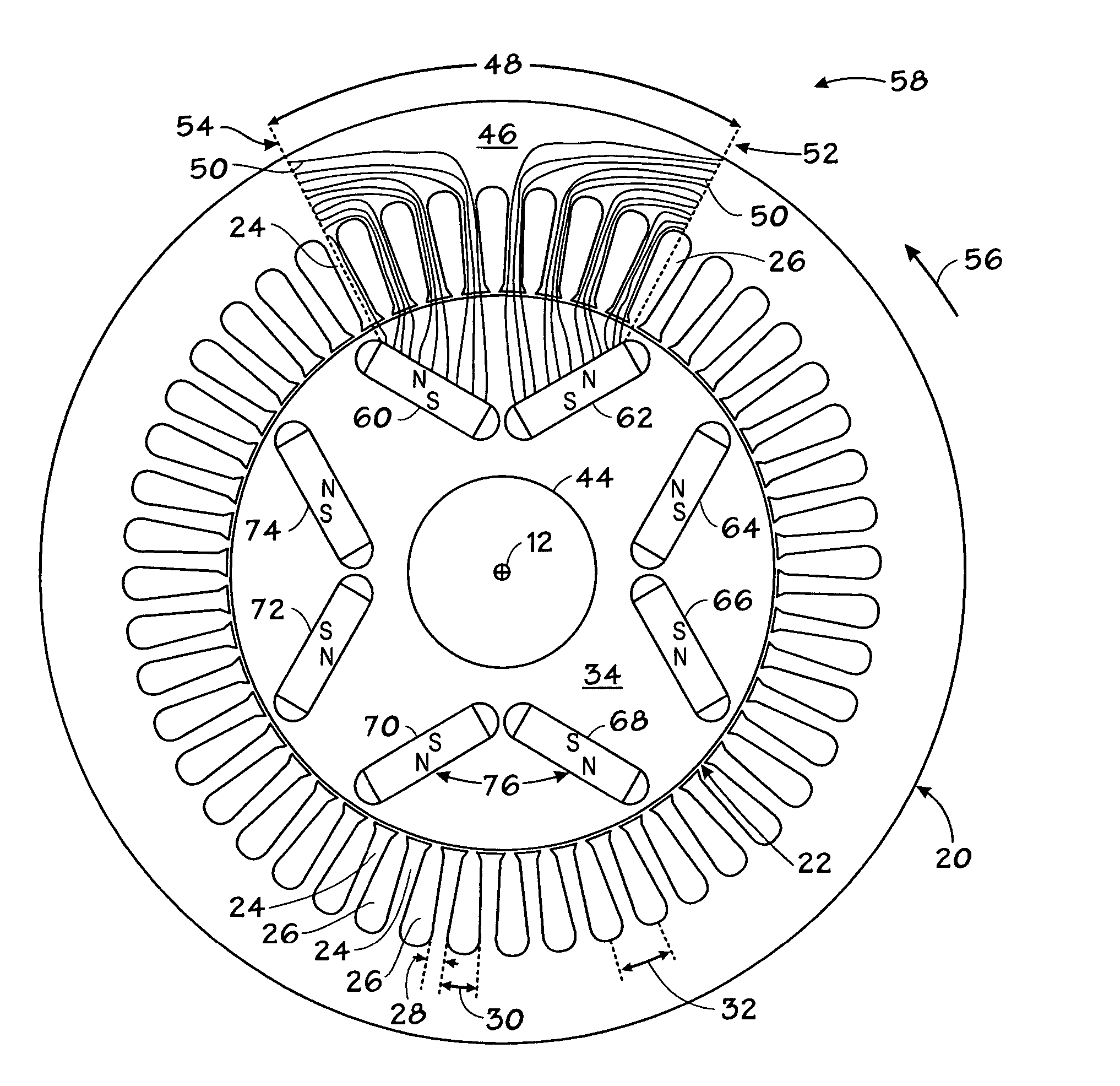
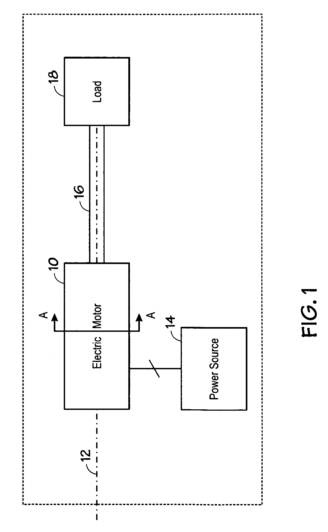
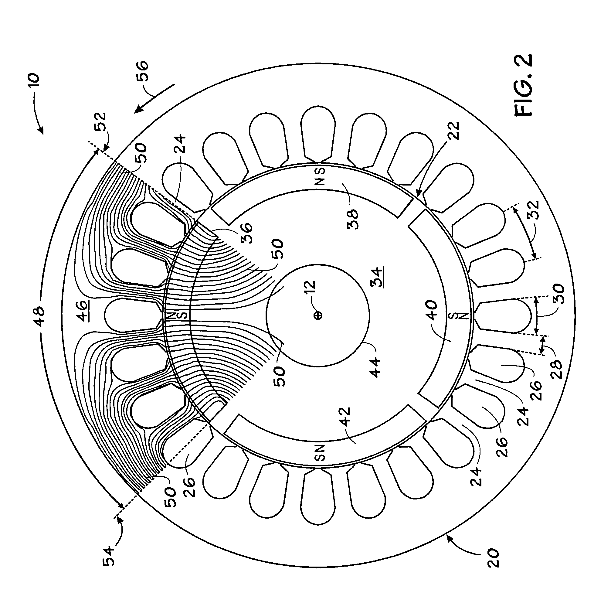
[0015]FIG. 1 illustrates an exemplary system that includes a motor 10 having an axis of rotation 12, a power source 14, a shaft 16, and a load 18. As explained further below, the motor 10 may generate minimal cogging torque. In subsequently discussed embodiments, the motor 10 includes a rotor with magnetic poles that are spatially desynchronized with teeth in a stator. To this end, in certain embodiments, the magnetic poles may have an angular width that is not an integer multiple of the pitch of the teeth. As the rotor rotates, when the leading edge of a magnetic pole is aligned with a tooth, the trailing edge of the magnetic pole is between teeth, and vise versa. Advantageously, some of these embodiments may mitigate the previously discussed cogging effect. It is believed that staggering the time at which the leading and trailing edges of a pole are aligned with stator teeth reduces the torque applied to the rotor as it rotates between teeth, as is explained in greater detail belo...


PUM


Abstract

A permanent magnet motor having a rotor and a stator and configured such that when the leading edge of each pole of the rotor aligns with a stator tooth the trailing edge of that pole is generally not aligned with a stator tooth.

Description

BACKGROUND[0001]The invention relates generally to electric machines and, more specifically, to permanent magnet electric machines with reduced cogging effects.[0002]Permanent magnet machines, such as a generator or an electric motor, typically include a rotor and a stator. For instance, in synchronous electric motors, the rotor may include permanent magnets to form magnetic poles. The magnetic poles are typically rotationally symmetrically disposed about the rotor. In these motors, the stator often includes a number of windings disposed between regularly spaced teeth. A time varying electric current passing through the windings creates a rotating magnetic field that interacts with the poles of the rotor. The magnetic field from the stator drives the rotor by repelling and / or attracting the magnetic poles of the rotor, thereby converting electrical energy into mechanical energy.[0003]Synchronous electric motors often generate a torque as they rotate between adjacent teeth. This torq...

Claims


Application Information

Patent Timeline
Patent Type & Authority Patents(United States)
IPC IPC(8): H02K21/12H02K1/27
CPCH02K1/278H02K1/2766H02K29/03H02K21/14
Inventor MELFI, MICHAEL J.
Owner BALDOR ELECTRIC COMPANY
Why Eureka
Try Eureka