Sound transducer for solid surfaces

a sound transducer and solid surface technology, applied in the direction of electrical transducers, deaf-aid sets, transducer details, etc., can solve the problems of difficulty in mounting speakers in a listening area without interfering with windows, doors, columns, etc., and achieve the effect of transferring more acoustical energy, reproducing more sound, and consistent and uniform frequency respons

Active Publication Date: 2008-06-10
MS ELECTRONICS
View PDF78 Cites 15 Cited by
  • Summary
  • Abstract
  • Description
  • Claims
  • Application Information

AI Technical Summary

Benefits of technology

[0013]The symmetrical magnet assemblies and voice coils drive the actuator with more power than prior art sound transducers and therefore reproduce more sound. Moreover, the symmetrical design provides a more consistent and uniform frequency response. The actuator foot is larger than actuators of prior art sound transducers and therefore transfers more acoustical energy without damaging the solid surface to further enhance the sound production and frequency response of the sound transducer.
[0014]The sound transducer may also include a pair of symmetrical suspension springs. The springs are stiffer than conventional accordion-edge suspensions and therefore better align the voice coils in the area of concentrated magnetic flux of the magnet assemblies. This creates more uniform and consistent movement of the voice coil and actuator and therefore more uniform and consistent sound reproduction and frequency response. Use of a pair of symmetrical suspension springs further improves the alignment of the voice coils.
[0015]The sound transducer also preferably includes an elongated shaft for coupling the actuator to the voice coils. Opposite ends of the elongated shaft are supported for linear movement by a pair of bearing tubes. The use of two spaced-apart bearing tubes stabilizes the shaft and attached voice coils, keeps the voice coils properly aligned in the magnetic flux of the magnet assemblies and prevents the voice coils from wobbling or other undesired movements that creates sound distortion. The spaced-apart bearing tubes also divide and balance the weight of the magnet assemblies and corresponding housing to reduce the amount of torque on the shaft and attached actuator and maintain the alignment of the shaft and voice coils regardless of the mounting configuration of the sound transducer. For example, if the actuator is mounted to a vertical wall, the shaft extends horizontally from the wall. The spaced-apart bearing tubes reduce the torque on the shaft and maintain the alignment of the shaft and voice coils against the force applied by the heavy magnet assemblies.

Problems solved by technology

Mounting numerous speakers in a listening area without interfering with windows, doors, columns, and other structural components of a room can be challenging.
However, some people find this mounting arrangement unsightly, especially when numerous speakers of varying sizes must be hung from the ceiling.
However, this method is considered unattractive by some people as well, because the speakers and their associated grills take up valuable wall and ceiling space and remain visible, thus detracting from the appearance of the room.
Although magnetostrictive speakers can be hidden and therefore solve many of the installation problems discussed above, they do not reproduce sound as accurately as conventional speakers and often exhibit non-uniform and less predictable frequency responses.
However, these prior art sound transducers are generally not powerful enough to move a rigid wall or other solid surface sufficiently to create a desirable level and quality of sound.
Moreover, such prior art transducers do not produce a uniform frequency response due to their construction.

Method used


Image

  • Sound transducer for solid surfaces
  • Sound transducer for solid surfaces
  • Sound transducer for solid surfaces

Examples


Embodiment Construction

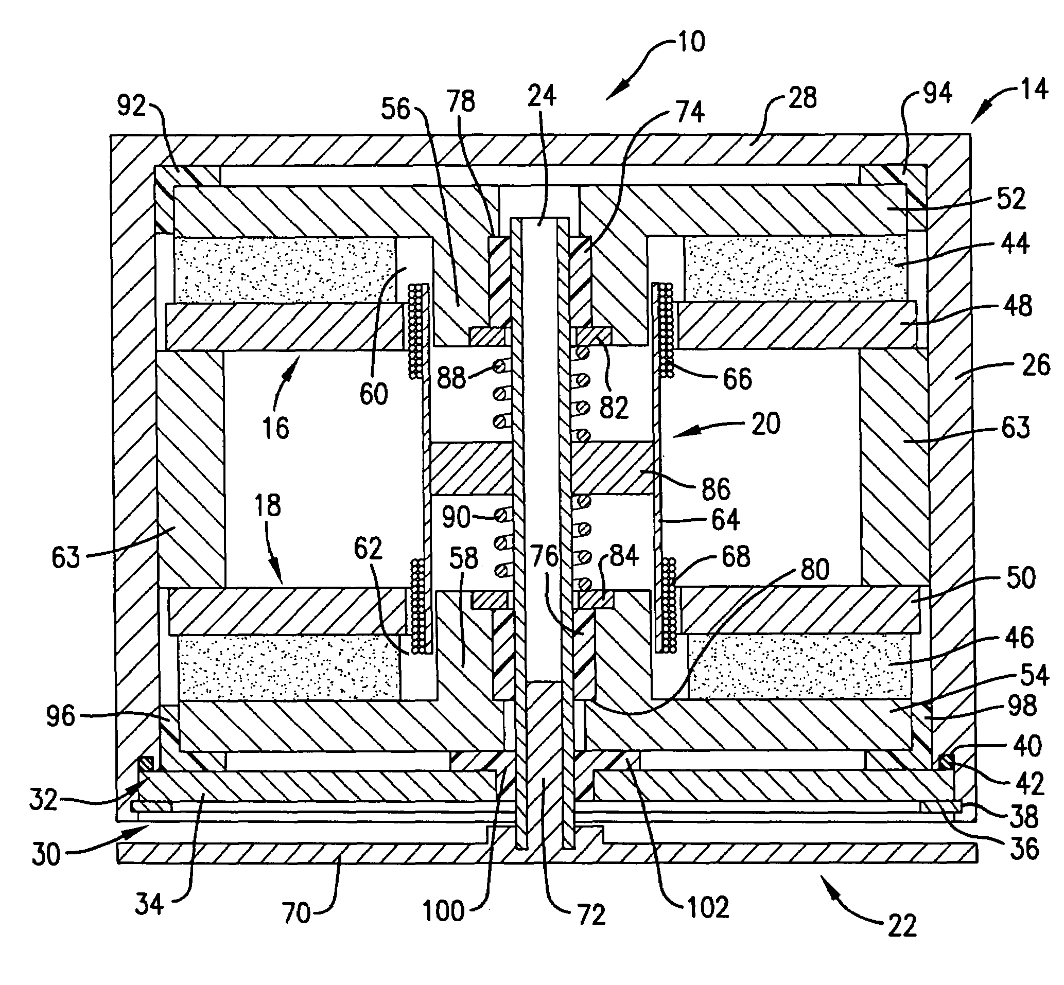
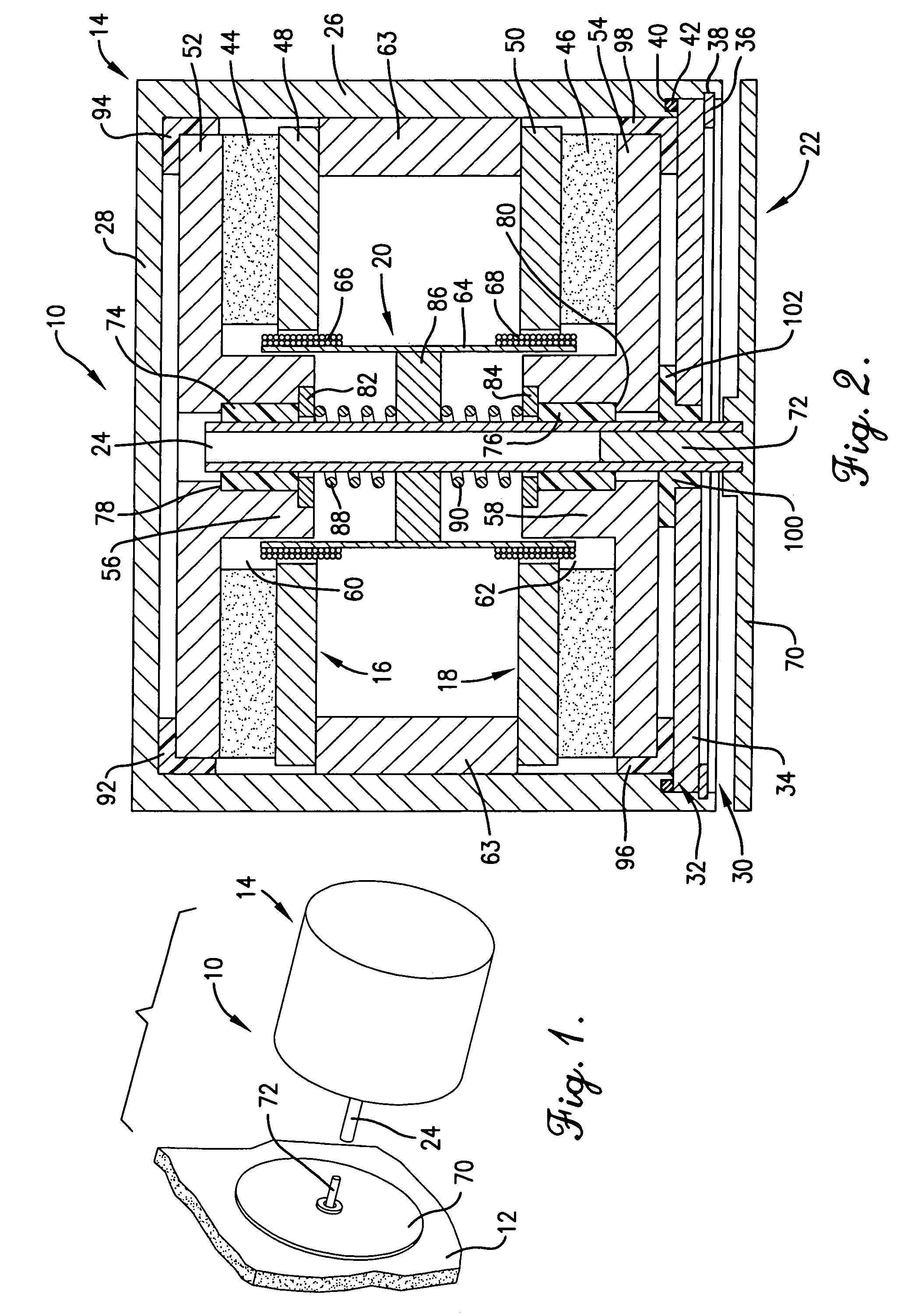
[0022]A sound transducer 10 constructed in accordance with a preferred embodiment of the present invention is shown in FIG. 1 attached to a solid surface 12 such as a wall of a room or other listening area. As explained in more detail below, the sound transducer 10 imparts acoustical energy directly to the solid surface 12 to vibrate the solid surface 12 in accordance with an applied audio signal to thereby produce sound.

[0023]The solid surface 12 may be constructed of any material or combination of materials such as drywall, glass, fiberglass, wood, or even metal; however, extremely thick materials such as concrete are not preferred because they do not transfer acoustical energy well enough to produce much usable sound. The sound transducer 10 is preferably mounted to an area of the solid surface 12 that is not directly attached to another more rigid surface. For example, when attached to a wall consisting of drywall supported by wooden studs, the sound transducer 10 is preferably ...


PUM


Abstract

A sound transducer (10) for imparting acoustical energy directly to a solid surface (12) while achieving the sound quality and frequency response found only in conventional diaphragm speakers. The sound transducer (10) comprises a pair of symmetrical magnet assemblies (16, 18), a pair of symmetrical voice coils (66, 68), and an actuator (22). The magnet assemblies (16, 18) each present an area of concentrated magnetic flux (60, 62). The symmetrical voice coils (66, 68) are positioned in the vicinity of the areas of concentrated magnetic flux and are operable to receive an alternating audio signal which causes the voice coils to move relative to the magnet assemblies. The actuator (22) moves with the voice coils and includes a foot (70) for coupling with a solid surface to impart movement to the solid surface and thereby produce sound when the voice coils receive the audio signal. The actuator (22) is coupled to the voice coils (66, 68) by an elongated shaft (24). The shaft (24) is supported for linear movement by a pair of spaced-apart bearings (74, 76).

Description

RELATED APPLICATIONS[0001]The present application is a continuation-in-part and claims priority benefit, with regard to all common subject matter, of an earlier-filed U.S. patent application titled “SOUND TRANSDUCER FOR SOLID SURFACES,” Ser. No. 11 / 012,925, filed Dec. 15, 2004. The above-identified non-provisional application is hereby incorporated by reference into the present application.BACKGROUND OF THE INVENTION[0002]1. Field of the Invention[0003]The present invention relates to audio systems and speakers. More particularly, the invention relates to an improved sound transducer for imparting acoustical energy directly to a solid surface such as a wall or pane of glass.[0004]2. Description of the Prior Art[0005]High performance audio systems and speakers continue to grow in popularity as more and more consumers install home theater systems in their homes, offices and other personal spaces. Such home theater systems typically consist of a high definition TV, projection TV, plasm...

Claims


Application Information

Patent Timeline
Patent Type & Authority Patents(United States)
IPC IPC(8): H04R25/00
CPCH04R9/063
Inventor COMBEST, CHRISTOPHER
Owner MS ELECTRONICS
Why Eureka
Try Eureka