Aerial sensor pod deployment system

a technology of sensor pods and deployment systems, which is applied in the direction of aircraft crew accommodation, transportation and packaging, fuselages, etc., can solve the problems of limited data collection from such sensors, limited field of view of aerial sensor platforms, and severe limitations in the field of view capabilities of sensors on the sensor platform, so as to maximize mission flexibility, stability and structural soundness, and flexibility. , to achieve the effect of increasing and decreasing the angle, maximizing the flexibility of mission, and reducing the cost of operation

Inactive Publication Date: 2008-06-17
WEST VIRGINIA UNIVERSITY
View PDF12 Cites 44 Cited by
  • Summary
  • Abstract
  • Description
  • Claims
  • Application Information

AI Technical Summary

Benefits of technology

[0010]An aspect of the present invention is a storable, rapidly deployable, roll-on / roll-off, two-palletized system. The first pallet assembly is an enclosure placed within the main cargo hold of the aircraft. This enclosure houses the sensor operators (personnel), electrical power conditioning, the control computers for the sensor array, and the communications equipment. The second assembly is a smaller pallet that attaches to the rear ramp of the aircraft. The system of the present invention maximizes mission flexibility, stability and structural soundness, field of view, ease of use to the operator, storability, modular attachment space, and flexibility for a wide range of remote sensing and communications technologies. The sensors deployed on this system thus have a useable field of view so that imaging sensors can “see” targets unobstructed. Major components of the system of the present invention include a gear reducer with attached rotation motor, a (linear) translation motor, and sensor pallet equipment. The electrical impact of the system of the present invention upon the power supplied by C-130 aircraft generators, even with numerous sensors mounted and deployed, is minimal. The sensor pallet deployment and recovery process may be carried out in automatic, manual, or emergency hand-crank (recovery only) mode. Deployment of the system of the present invention includes initial loading of the pallets into an aircraft and mechanical translation and rotation of the sensor pod into position beneath the aircraft.
[0011]The present invention compensates for obstructions and specific line of site of targets. The present invention controls the angle, with respect to the ground, of the sensor pod. The present invention can increase and decrease the angle, with respect to the ground, of the sensor pod during an ongoing mission.

Problems solved by technology

Aerial sensor platforms have always experienced limitations in terms of their field of view with respect to a ground target.
The positioning (side doors, rear cargo ramps, sensor pods attached to plane structures, etc.) of a sensor platform on the plane can severely limit the field of view capabilities of the sensors on the sensor platform.
Data collected from such sensors is therefore limited.
The field of view of such boom-extended sensors is limited by the body of the aircraft.
Such sensors may not be able to collect data from areas in front of the aircraft.
Additionally, the use of boom-extended sensors can be problematic at high altitudes.
Furthermore, sensors placed on the end of a boom may not have the required stability for precision data collection, nor would the sensors be protected from weather and high drag forces experienced during flight.

Method used


Image

  • Aerial sensor pod deployment system
  • Aerial sensor pod deployment system
  • Aerial sensor pod deployment system

Examples


Embodiment Construction

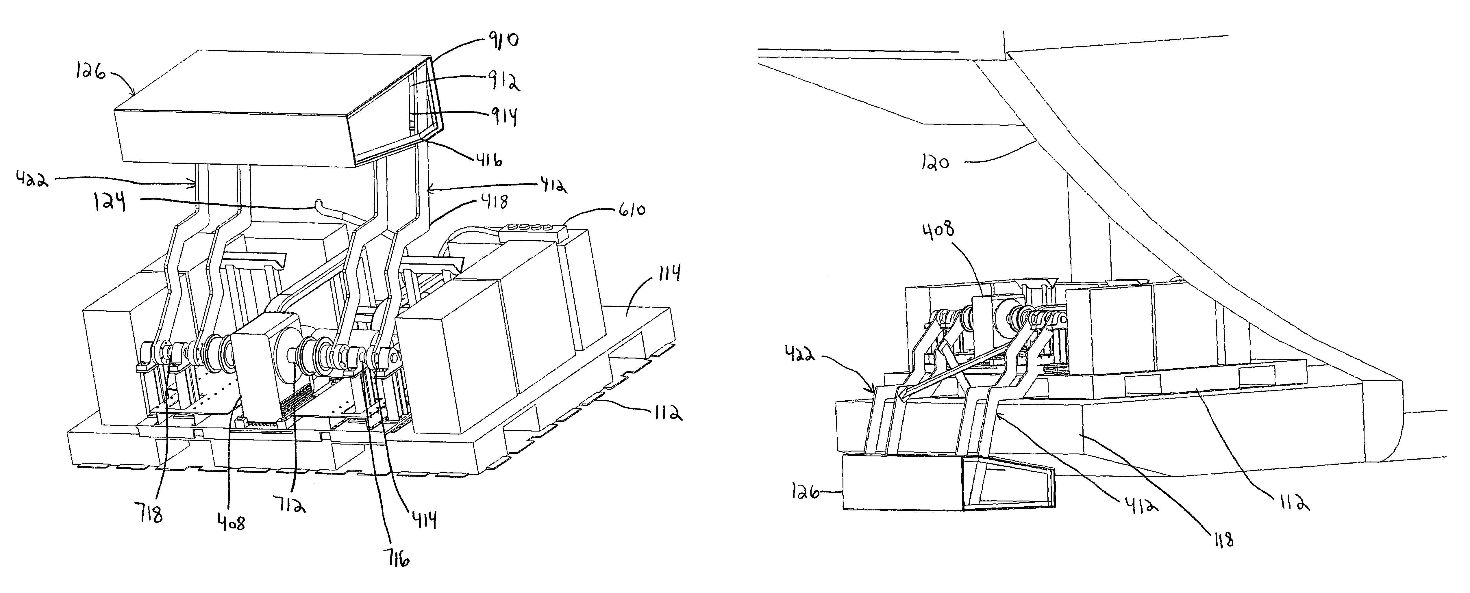
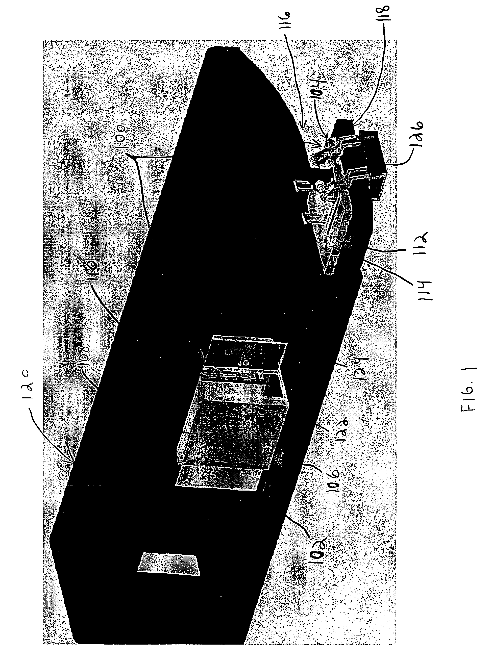
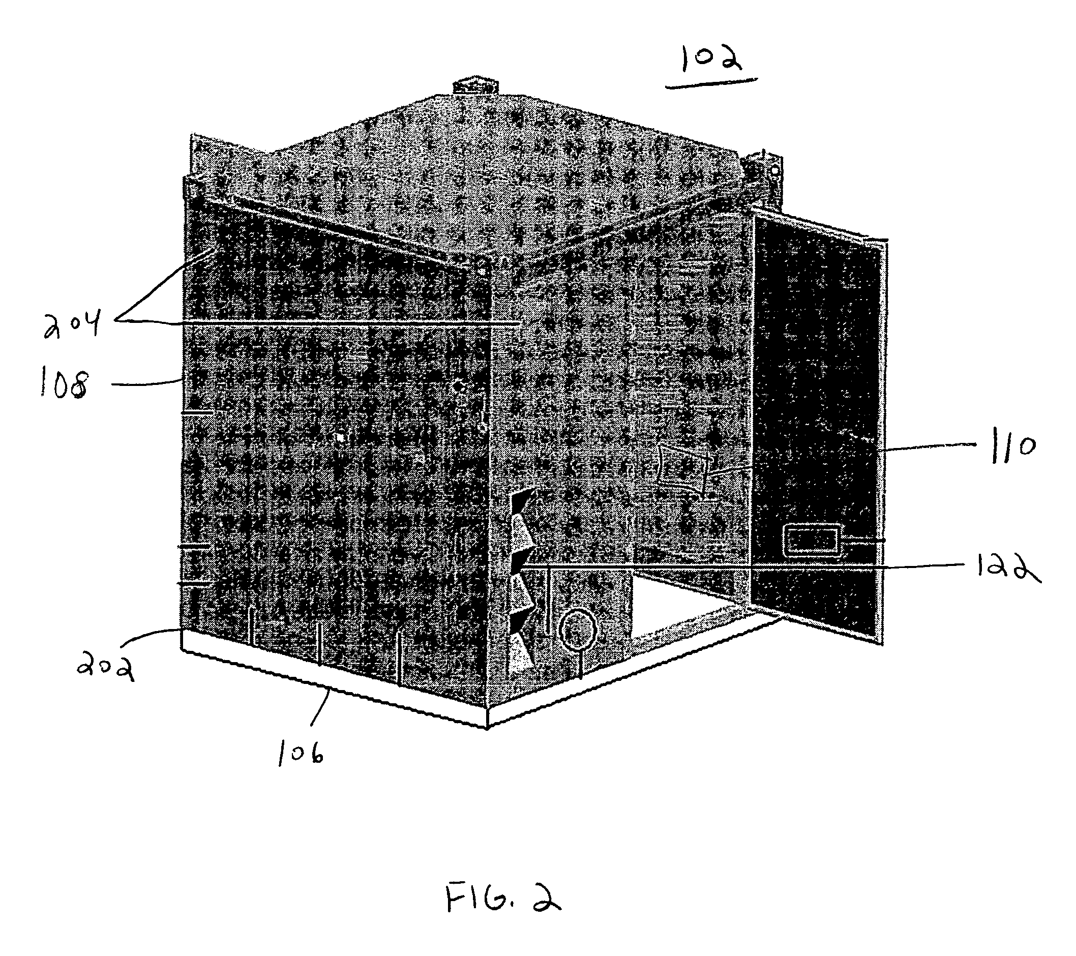
[0030]The present invention is directed to a roll-on / roll-off system for deploying a sensor pod out an opening on an aircraft such that sensors mounted to the sensor pod have an increased or unobstructed field of view. With reference to the drawings, and in particular to FIG. 1, an embodiment of an aircraft-borne sensor pod deployment system 100 comprises an operator station 102 and a sensor pallet system 104. The operator station 102 comprises an operator station base platform 106, a shelter box 108, and an operator station computer 110. The sensor pallet system 104 comprises a sensor pallet base platform 112 and a sensor pod 126. The operator station 102 is preferably positioned inside a fuselage or cargo hold of an aircraft 120. The sensor pallet system 104 is preferably positioned near the operator station 102 inside the aircraft 120, and also near an opening 116 on the aircraft 120, such as near the opening 116 created by the lower cargo ramp and upper cargo door in the rear of...


PUM


Abstract

A roll-on/roll-off, aircraft-borne sensor pod deployment system having an operator station and a sensor pallet system and method of using same. The operator station has a base platform, a shelter box mounted on the base platform for accommodating a human operator, and a computer installed inside the shelter box. The sensor pallet system has a base platform, a linear system mounted on the base platform, a rotational system mounted on the linear system, a mechanical arm attached to the rotational system, a sensor pod attached to the mechanical arm, and an electrical control system that provides power to the deployment system and controls movements of the sensor pallet system. In operation, the sensor pod can be retracted into a compact, stowing position, or extended out an opening in the aircraft for an unobstructed field of view. The deployment system optionally includes an apparatus and method for sealing the aircraft opening.

Description

STATEMENT REGARDING FEDERALLY SPONSORED RESEARCH OR DEVELOPMENT[0001]The U.S. Government has a paid-up license in this invention and the right in limited circumstances to require the patent owner to license others on reasonable terms as provided for by the terms of GSA Contract No. GST0404DE141 awarded by the National Guard Bureau Counterdrug Office.BACKGROUND OF THE INVENTION[0002]1. Field of the Invention[0003]This invention relates to sensor deployment systems, and in particular, to an aircraft-borne system for deploying a sensor pod with an unobstructed field of view.[0004]2. Description of the Related Art[0005]The technology of aerial sensors has become an increasingly popular field of research and development for military and civilian aircraft. Aerial sensor platforms have always experienced limitations in terms of their field of view with respect to a ground target. The positioning (side doors, rear cargo ramps, sensor pods attached to plane structures, etc.) of a sensor plat...

Claims


Application Information

Patent Timeline
Patent Type & Authority Patents(United States)
IPC IPC(8): B64C1/20B64C1/14B64C1/22B64D47/00
CPCB64C1/1415B64C1/22B64D47/00
Inventor SMITH, JAMES E.NUTTER, JR., ROY S.THOMPSON, GREGORY J.WOWCZUK, ZENOVY S.ANGLE, II, GERALD M.
Owner WEST VIRGINIA UNIVERSITY
Why Eureka
Try Eureka