Vehicular headlamp

a headlamp and headlamp technology, applied in the field of headlamps, can solve the problems of reducing the ability to achieve thin formation of lamp pieces by adopting semiconductor light emitting elements as light sources, unable to prolong the luminous intensity distribution pattern sideways, etc., to achieve the effect of preventing glare against the driver of a car running on the opposite lane, promoting indirect illumination effect of lamp pieces, and effective restraint of non-uniform luminous intensity distribution

Inactive Publication Date: 2008-06-17
KOITO MFG CO LTD
View PDF11 Cites 30 Cited by
  • Summary
  • Abstract
  • Description
  • Claims
  • Application Information

AI Technical Summary

Benefits of technology

[0020]The present invention has various advantages. As shown by the above-described constitution, the vehicular headlamp according to the invention is constituted to form the luminous intensity distribution pattern for low beam by irradiating light from the plurality of lamp piece units each constituting the light source by the semiconductor light emitting element, as the plurality of lamp piece units, at least one side irradiating lamp piece unit is provided other than at least one front irradiating lamp piece unit, the respective light irradiating lamp piece units are constituted by the lamp piece units of the parabolic pillar type and therefore, the luminous intensity distribution pattern prolonged sideways can be formed by the irradiated light, thereby, the wide diffusing region of the luminous intensity distribution pattern for low beam can easily be formed.
[0028]Although in the above-described constitution, the specific constitution of the respective front irradiating lamp piece units is not particularly limited as described above, when each of the respective lamp piece units is constituted to include a projecting lens and the reflector for reflecting light from the light source in the front direction on the rear side of the projecting lens and constituted as a lamp piece unit of a so-to-speak projector type in which the reflecting face of the reflector is constituted to substantially converge light from the light source reflected by the reflecting face at a vicinity of a focal point on the rear side of the reflecting lens, a rate of utilizing light flux with respect to light from the light source can sufficiently be increased easily, thereby, a number of the front irradiating lamp piece units can be restrained to be small. Further, by constituting the respective front irradiating lamp piece units by lamp piece units of the projector type having an outer shape rounded as a whole, even when the surface shape of the vehicular headlamp is flexed to the rear side, a larger depth space for arranging the front irradiating lamp piece unit thereby can be prevented from being needed.

Problems solved by technology

When the lamp piece unit of the parabolic pillar type is arranged to direct to the front direction of the vehicle in the vehicular headlamp having the surface shape flexed to the rear side, there is a related art problem in that a portion of diffused and reflected light from the reflector is blocked by other lamp piece constituting member and the luminous intensity distribution pattern prolonged sideways cannot be formed.
Therefore, there is a related art problem in that the ability to achieve thin formation of the lamp piece by adopting the semiconductor light emitting element as the light source is reduced.

Method used


Image

  • Vehicular headlamp
  • Vehicular headlamp
  • Vehicular headlamp

Examples


first embodiment

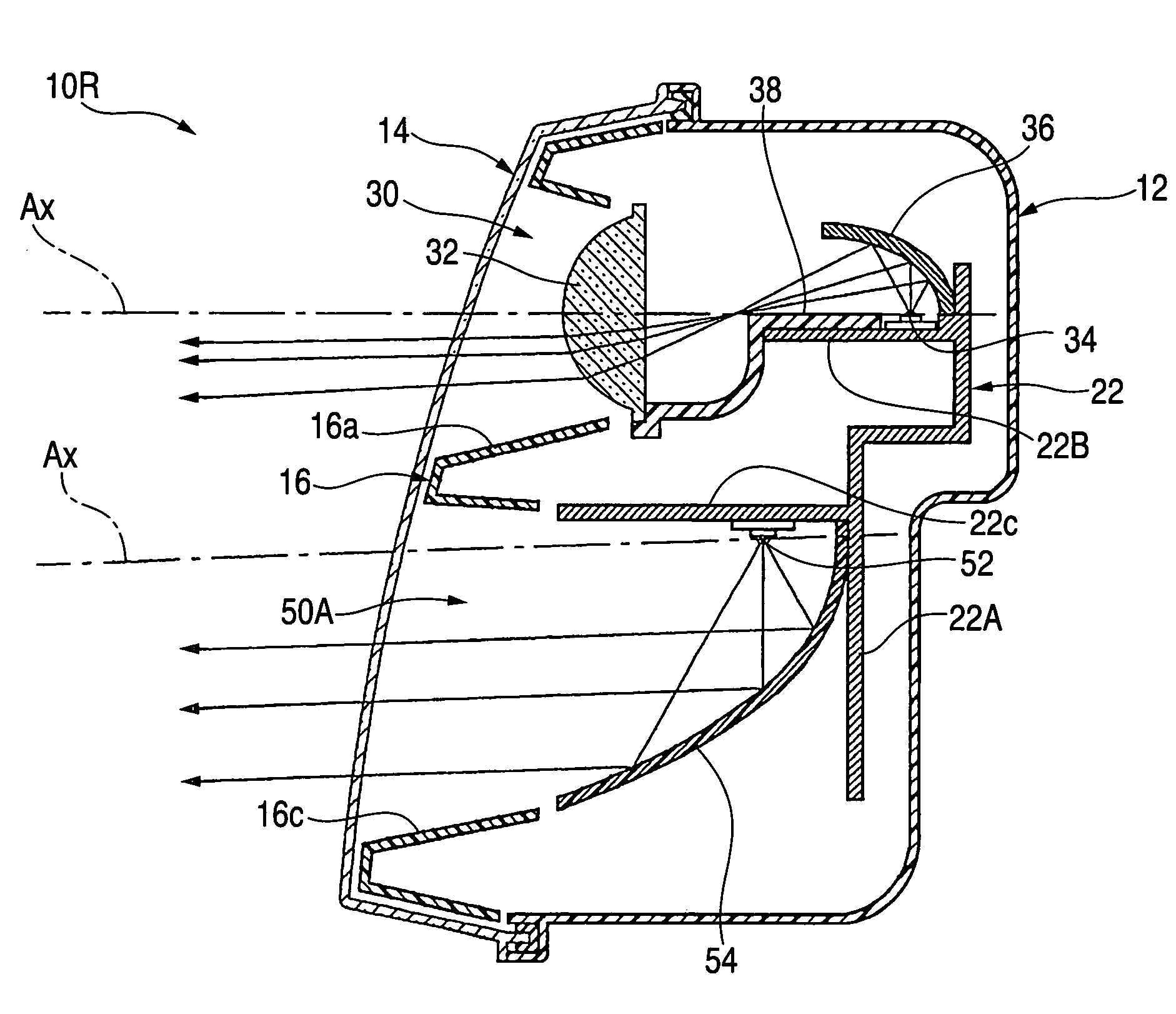
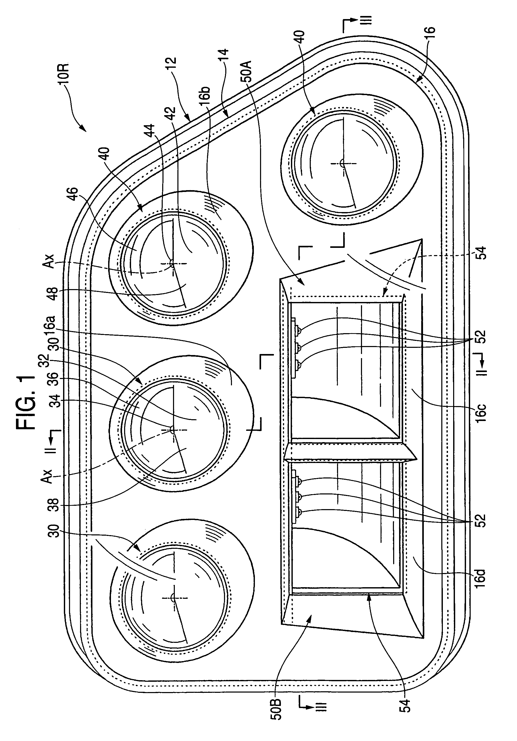
[0081]As described above, the luminous intensity distribution pattern PL for low beam is formed by irradiating light from the six lamp piece units 30, 40, 50A, 50B constituting light sources of the semiconductor light emitting elements. Of the six lamp piece units, other than the four front irradiating lamp piece units 30, 40, two side irradiating lamp piece units 50A, 50B are provided. The respective side irradiating lamp piece units 50A, 50B are constituted as the lamp piece units of the parabolic pillar type. Therefore, the luminous intensity distribution patterns PL 3A, PL 3B that are prolonged sideways can be formed by irradiated light thereof to enable easy formation of the wide diffusing region of the luminous intensity distribution pattern PL for the low beam.

[0082]In this case, the lamp piece units 50A, 50B of the parabolic pillar type are constituted as the side irradiating lamp piece units. Therefore, when the surface shape of the vehicular headlamp 10R is flexed to the ...

second embodiment

[0095]FIG. 14 is a perspective view showing a luminous intensity distribution pattern for a low beam formed on the imaginary vertical screen by light irradiated from the vehicular headlamp 10L to a front direction.

[0096]The luminous intensity distribution pattern PL for low beam is substantially similar to the case of the luminous intensity distribution pattern PL for low beam shown in FIG. 10 with regard to the luminous intensity distribution patterns PL 1, PL 2 formed by irradiating light from the front irradiating lamp piece units 30, 40. However, with regard to the luminous intensity distribution patterns PL 3A, PL 3B formed by irradiating light from the side irradiating lamp piece units 50A, 50B, the luminous intensity distribution pattern PL for low beam is brought into a positional relationship symmetric with the luminous intensity distribution pattern PL for low beam of FIG. 10 in the left and right direction.

[0097]Also in the second embodiment, although the surface shape o...


PUM


Abstract

Lamp piece units in a parabolic pillar type capable of forming a luminous intensity distribution pattern prolonged sideways are formed as side irradiating lamp piece units. Thereby, a portion of diffused and reflected light from reflectors of the respective side irradiating lamp piece units is prevented from being blocked by other lamp piece constituting members, even when a surface shape of a vehicular headlamp is flexed to the rear side. Further, although the respective side irradiating lamp piece units are constituted by the lamp piece units of the parabolic pillar type having an angular outer shape as a whole, a large depth space for arranging the units is dispensed with.

Description

[0001]The present application claims foreign priority under 35 USC 119 based on Japanese Patent Application No. 2003-374061, filed Nov. 4, 2003, the contents of which is incorporated herein by reference.BACKGROUND OF THE INVENTION[0002]1. Technical Field[0003]The present invention relates to a vehicular headlamp that forms a luminous intensity distribution pattern for a low beam by irradiating light from a plurality of lamp piece units, each of which constitutes a light source by a semiconductor light emitting element.[0004]2. Related Art[0005]In the related art, a vehicular headlamp is able to form a luminous intensity distribution pattern for a low beam having a cutoff line at an upper end edge thereof, to ensure front recognizability of a driver of one's own car as much as possible while preventing the casting of glare to a driver of a car running on the opposite side or the like.[0006]In such a case, Japanese publication JP-A-2003-123517 describes a vehicular headlamp constitute...

Claims


Application Information

Patent Timeline
Patent Type & Authority Patents(United States)
IPC IPC(8): F21V14/00F21S8/12F21S8/10F21V13/00F21W101/10F21Y101/02
CPCB60Q1/0041F21S48/1159F21S48/1163F21Y2101/02F21S41/155F21Y2115/10F21S41/148
Inventor SAZUKA, KIYOSHIISHIDA, HIROYUKITATSUKAWA, MASASHI
Owner KOITO MFG CO LTD
Why Eureka
Try Eureka