Audio jack connector

a technology of jack connector and connector, which is applied in the direction of coupling device connection, two-part coupling device, and securing/insulating coupling contact member, etc., can solve the problem that the terminal cannot provide enough elastic force to press against the plug, and achieve the effect of even more elastic force and friction

Inactive Publication Date: 2008-06-17
CHENG UEI PRECISION IND CO LTD
View PDF6 Cites 23 Cited by
  • Summary
  • Abstract
  • Description
  • Claims
  • Application Information

AI Technical Summary

Benefits of technology

[0007]When the audio jack connector mates with the plug, the first set of terminals with simple supported beam structure of the audio jack connector abut against the plug for transmitting signal. The resilient arm between the side arms of the fixed portion can provide even more elastic force and friction between the plug and the first set of terminals.

Problems solved by technology

During the process of inserting, the deformation of the terminal oversteps the bounds of the terminals easily, and then the terminal can't provide enough elastic force to press against the plug and enough friction to keep the plug hold firmly in the audio jack connector to transmit signal stably.

Method used


Image

  • Audio jack connector
  • Audio jack connector
  • Audio jack connector

Examples


Embodiment Construction

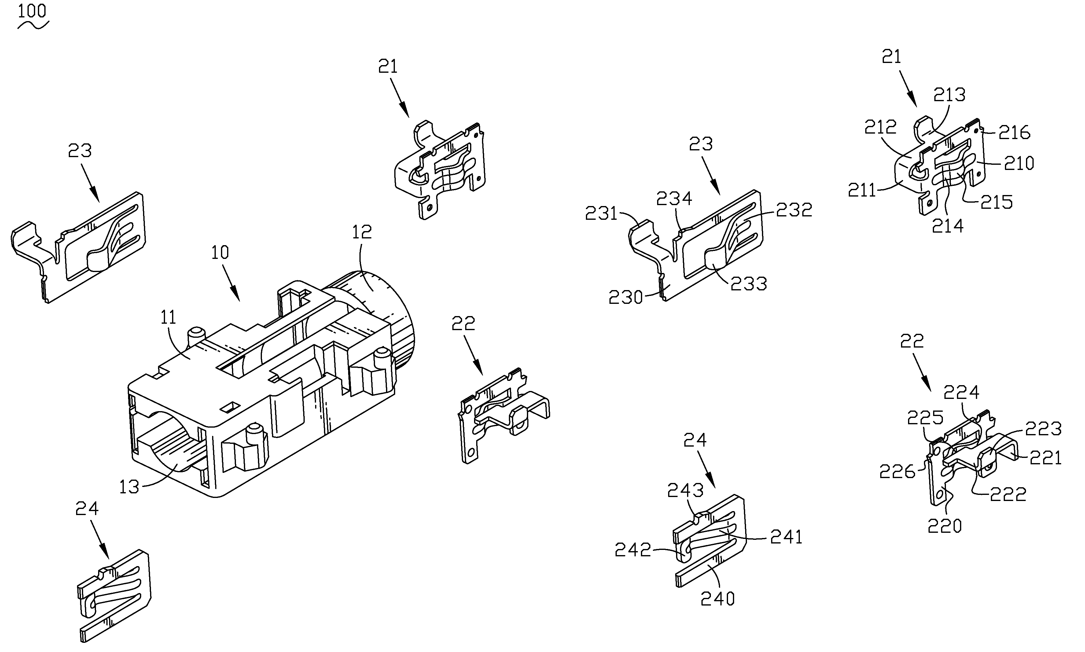
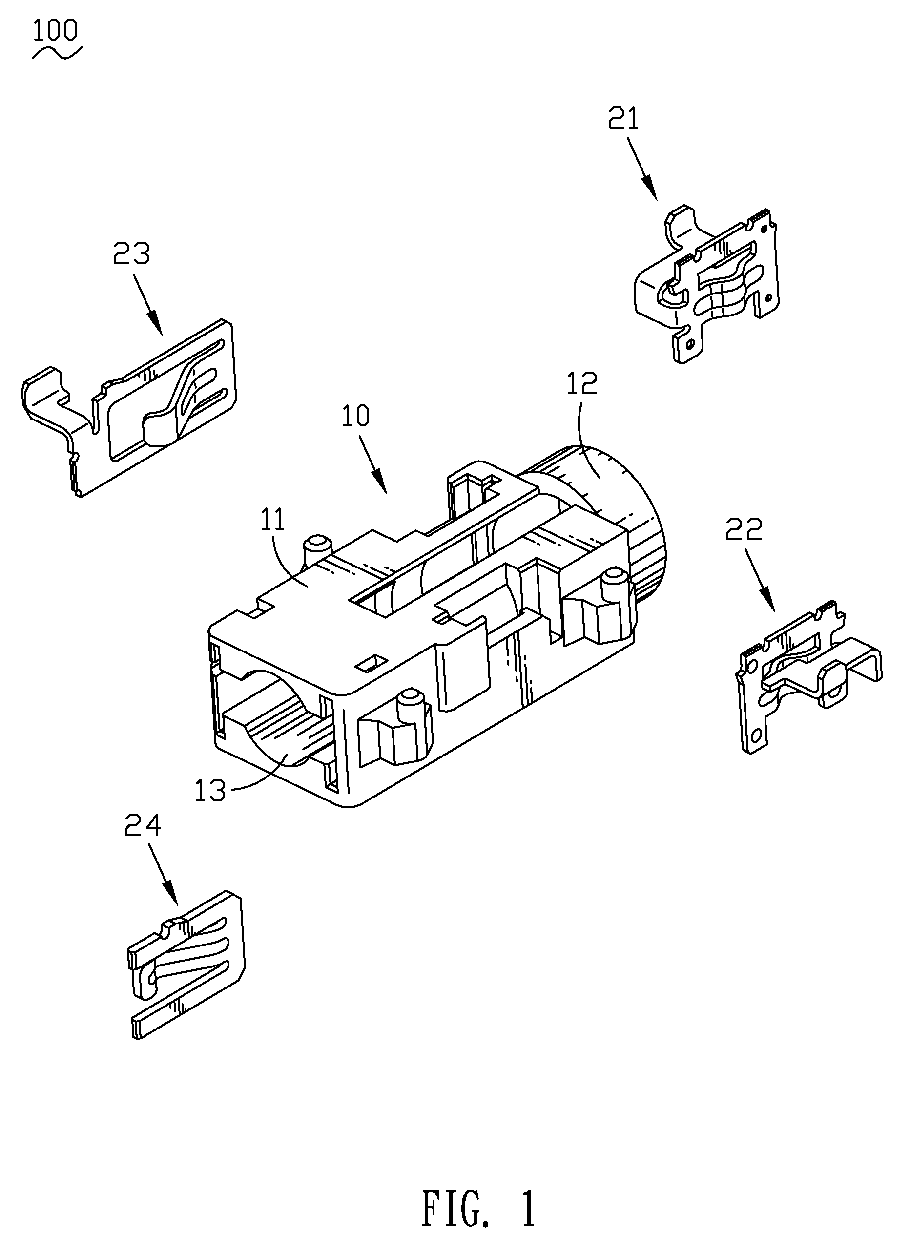
[0014]With reference to FIG. 1, an audio jack connector 100 includes an insulative housing 10 and a terminal group received in the insulative housing 10. The housing 10 has an oblong body 11, a mating portion 12 extending from one end of the body 11 along an axis direction of the body 11, and an insertion hole 13 defined in the mating portion 12 and passing through the body 11 and mating portion 12 along the axis direction of the body 11.

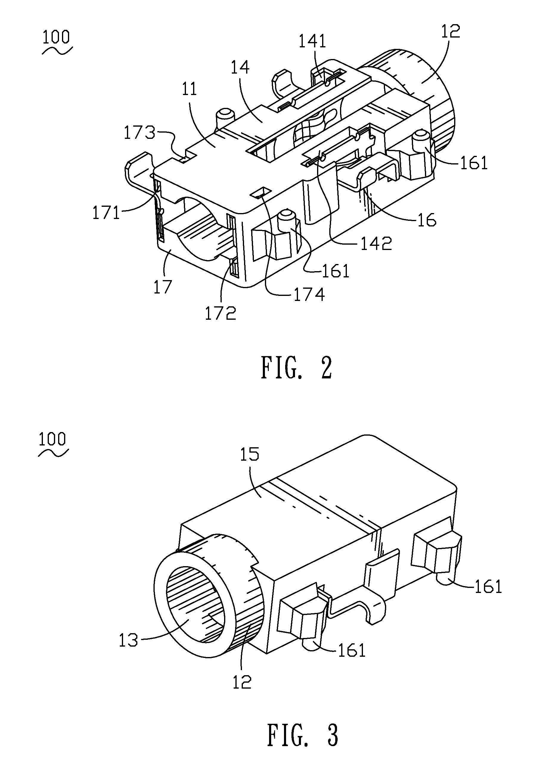
[0015]Referring to FIG. 2 and FIG. 3, the body 11 has a top wall 14, a bottom wall 15, two sidewalls 16 and a back wall 17. The top wall 14 defines a first slot 141 and a second slot 142 at the opposite sides of the front and is connected with the insertion hole 13. The sidewalls 16 have a plurality of location pegs 161 which can be inserted into proper locations of a Printed Circuit Board (not shown). The back wall 17 defines a third slot 171 and a fourth slot 172 at two opposite sides of the rear and is connected with the insertion hole 13. A firs...


PUM


Abstract

An audio jack connector includes an insulative housing and a terminal group received in the insulative housing. The housing has a body, a mating portion extending from one end of the body along an axis direction of the body and an insertion hole defined in the mating portion and passing through the body and mating portion along the axis direction of the body. At least slots connected to the insertion hole are defined in the body. The terminal group includes a first set of terminals with simple supported beam structure and a second set of terminals with cantilever beam structure. The first set of terminals with simple supported beam structure have an U-shaped fixed portion with two side arms defined at the opposite sides of the fixed portion. A resilient arm connects the side arms together. The resilient arm has a contact portion at the middle, the contact portion projects inward into the insertion hole, so the outer surface of the first resilient arm is formed as a concave.

Description

BACKGROUND OF THE INVENTION[0001]1. Field of the Invention[0002]The present invention relates to an audio jack connector, and more particularly to an audio jack connector which increases the interference action between a plug and terminals.[0003]2. The Related Art[0004]Video and music equipments develop quickly in recent years. The stability for an audio jack connector matching with a plug is required. A conventional audio jack connector includes an insulative housing and a plurality of terminals received therein. The terminal is bent to form a cantilever beam shape by a conductive material. When one end of the terminal presses against a plug, the other end of the terminal is received in the insulative housing. During the process of inserting, the deformation of the terminal oversteps the bounds of the terminals easily, and then the terminal can't provide enough elastic force to press against the plug and enough friction to keep the plug hold firmly in the audio jack connector to tr...

Claims


Application Information

Patent Timeline
Patent Type & Authority Patents(United States)
IPC IPC(8): H01R24/04H01R24/58
CPCH01R24/58H01R13/41H01R2105/00H01R12/7052H01R12/707
Inventor WU, YIN-LUNGCHEN, MING-CHIANGSONG, MIN
Owner CHENG UEI PRECISION IND CO LTD
Why Eureka
Try Eureka