Process for in situ coating of turbo-machine components

a technology for turbo-machine components and in situ coating, which is applied in the direction of machines/engines, mechanical equipment, light and heating equipment, etc., can solve the problem of taking a long time for all the individual parts to be coated, and achieve the effect of reducing maintenance time and associated downtime, and considerably shortening the maintenance time of the turbin

Inactive Publication Date: 2008-06-17
SIEMENS AG
View PDF29 Cites 8 Cited by
  • Summary
  • Abstract
  • Description
  • Claims
  • Application Information

AI Technical Summary

Benefits of technology

[0012]The maintenance time for a turbine is considerably shortened by the process according to the invention, since, for example in the case of a gas turbine, there is no need to wait for the turbine and turbine housing to have cooled, and / or there is no need for forced cooling, and since it is not necessary to remove all the feed lines and outer parts of the housing. Also, the turbine does not have to be reassembled and started up again. This considerably reduces the maintenance time and the associated downtime for the operator of a turbine and obviates the need for heavy machines required to lift the housing parts.

Problems solved by technology

In the case of large machines, a rotor is composed of a large number of individual parts (a plurality of disks each having a plurality of turbine blades), which are coated individually or in groups, and consequently it takes a long time for all the individual parts to be coated.

Method used


Image

  • Process for in situ coating of turbo-machine components
  • Process for in situ coating of turbo-machine components
  • Process for in situ coating of turbo-machine components

Examples


Embodiment Construction

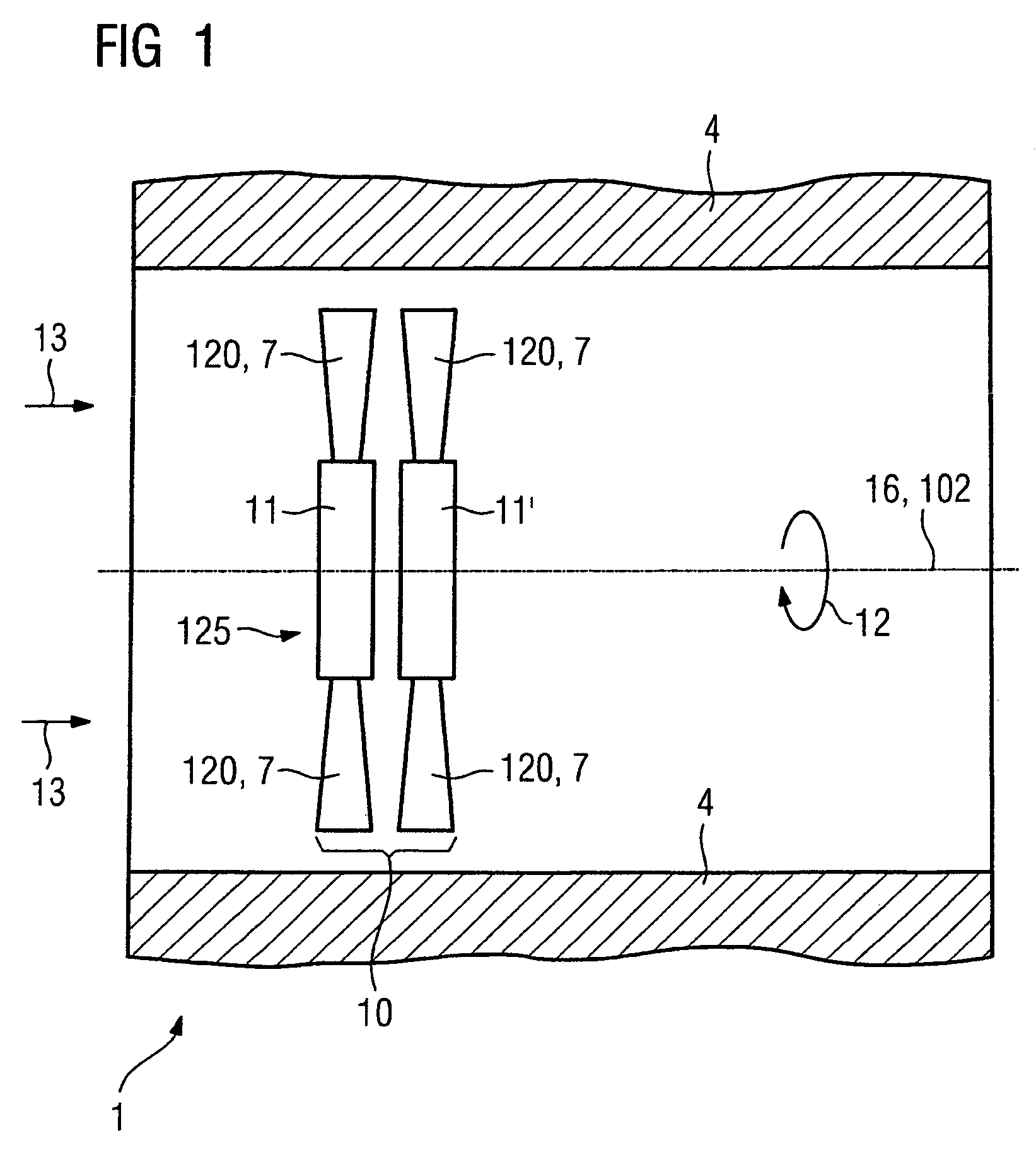
[0019]FIG. 1 shows an apparatus 1 which includes a turbomachine with a rotor 10.

[0020]The rotor 10 is to be coated within the interior of a housing 4.

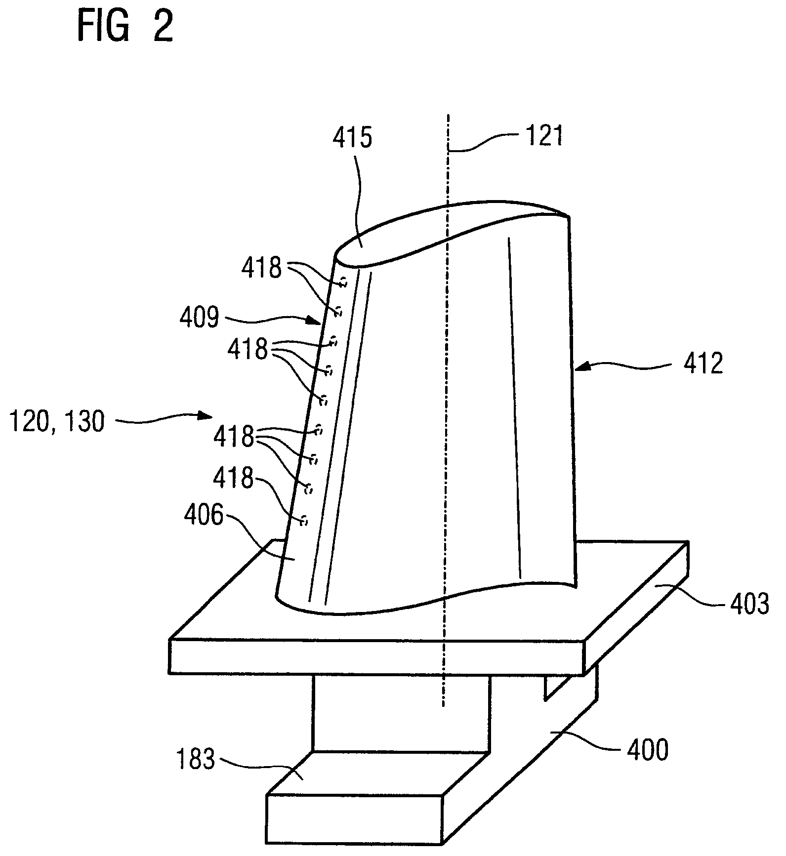
[0021]FIG. 1 diagrammatically depicts how the process according to the invention is to be carried out in order to coat the rotor 10. The rotor 10 comprises a plurality of parts 7, 120. In the case of a rotor 103 for a turbine 100, 300, 303 or of a compressor 105, the rotor 10, 103 has, for example, at least one disk 11, 11′133 (FIG. 4), on which a plurality of turbine blades 120, 354 (FIG. 2, 4, 5) are arranged in a radial orientation distributed over the circumference.

[0022]The rotor 10 may comprise a plurality of disks 11, 11′ each having a plurality of turbine blades 120, 354. A row 125 comprises, for example, a disk 11, 133 (FIG. 4) with turbine rotor blades 120.

[0023]The rotor 10, 103 is still arranged in its housing 4, 138 (FIG. 4) and can be rotated about a rotatable axis 16, 102 (FIG. 4).

[0024]The housing 4, 138 is, for example...


PUM

PropertyMeasurementUnit
temperatureaaaaaaaaaa
resistance to corrosionaaaaaaaaaa
circumferenceaaaaaaaaaa

Abstract

A method for coating a component of a turbo-machine. The method allows arranging a turbine rotor in the turbo-machine and introducing a coating material into the interior of the turbo-machine such that the rotor is coated. The rotor is rotated while it is being coated.

Description

CROSS REFERENCE TO RELATED APPLICATION[0001]This application claims priority of the European application No. 04028484.6 EP filed Dec. 01, 2004, which is incorporated by reference herein in its entirety.FIELD OF THE INVENTION[0002]The invention relates to a process for coating a component in accordance with the preamble of the claims.BACKGROUND OF THE INVENTION[0003]Components are often provided with layers in order to achieve a certain function, such as for example resistance to corrosion, oxidation and / or heat (thermal barrier). In this case, the coated components may also be rotating components, such as for example blades of a compressor or a turbine of a gas turbine installation which have layers protecting against erosion or heat. In the case of large machines, a rotor is composed of a large number of individual parts (a plurality of disks each having a plurality of turbine blades), which are coated individually or in groups, and consequently it takes a long time for all the ind...

Claims


Application Information

Patent Timeline
Patent Type & Authority Patents(United States)
IPC IPC(8): B05D7/22
CPCF01D5/005F01D5/288F23M5/00F23R3/007F23M2900/05004Y02T50/67F05D2230/90F05D2300/611F05D2230/40Y02T50/60
Inventor FISCHER, MARCUSPFEIFFER, ELMAR
Owner SIEMENS AG
Why Eureka
Try Eureka