Power amplifier with controllable feedback loop

a feedback loop and power amplifier technology, applied in the direction of gain control, positive feedback circuit arrangement, gain control, etc., can solve the problem of difficulty in providing the same output power for several frequency bands that shall be covered by the power amplifier, and achieve the effect of improving gain versus frequency behavior, gain and stability control, and sufficient gain and stability control

Active Publication Date: 2008-06-17
ALCATEL LUCENT SAS
View PDF7 Cites 10 Cited by
  • Summary
  • Abstract
  • Description
  • Claims
  • Application Information

AI Technical Summary

Benefits of technology

[0006]Due to the use of the feedback transistor within the RF path of the aforementioned feedback loop having in addition a capacitor in the RF path and an inductive element in the DC feed path, a certain gain and stability control of the amplifier can be achieved. This gain and stability control is sufficient to compensate gain variation versus the used frequency range. Such a feedback loop is used to adjust the output power at different frequency bands. The invention improves gain versus frequency behavior of wideband power amplifiers (e.g. within the preamplification chain) and thus improves output power behavior of multi-band capable frontends, for example UMTS base stations or mobile terminals. Further, the invention makes it possible to save variable attenuators or up to now conventional used variable gain amplifier stages within the amplification chain of multi-band capable frontends and thereby provides a robust and cheap solution of the gain variation problem.

Problems solved by technology

Since wideband power amplifiers often show gain variations versus the used frequency range, it is difficult to provide the same output power for several frequency bands that shall be covered by the power amplifier.

Method used


Image

  • Power amplifier with controllable feedback loop
  • Power amplifier with controllable feedback loop
  • Power amplifier with controllable feedback loop

Examples


Embodiment Construction

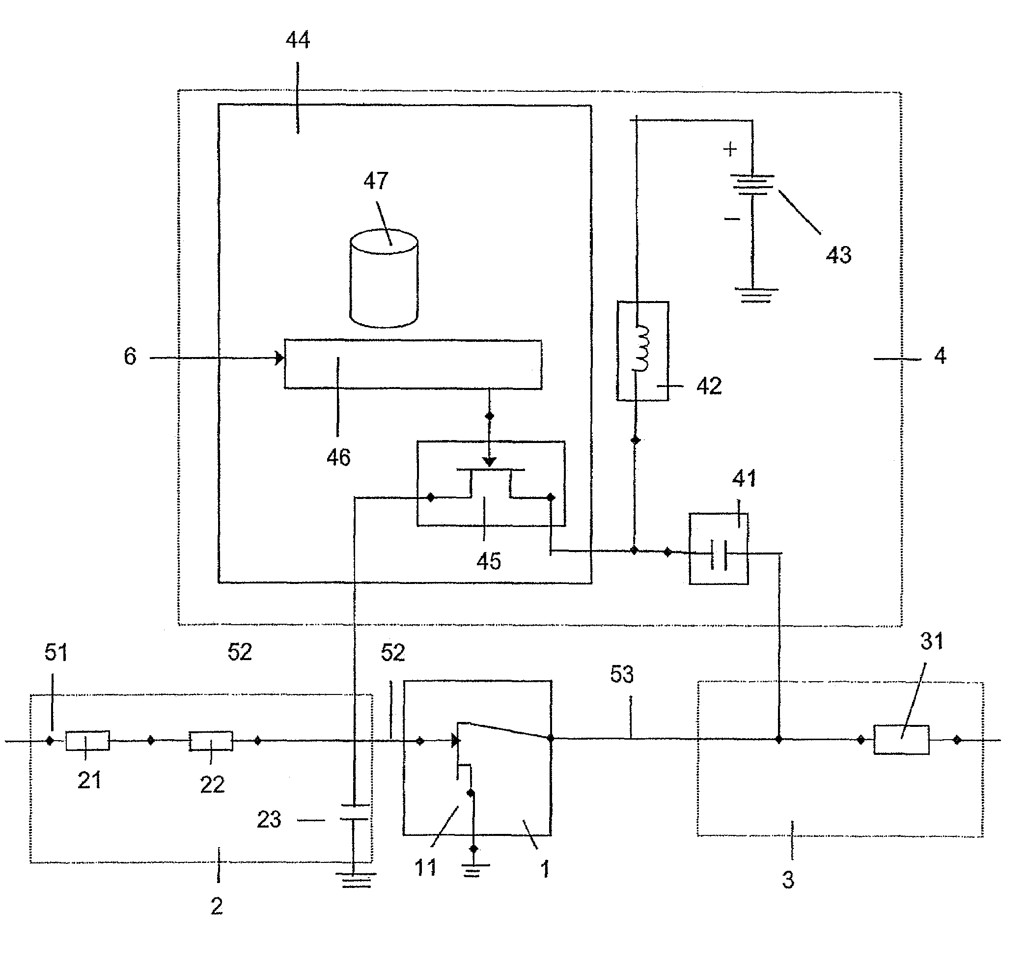
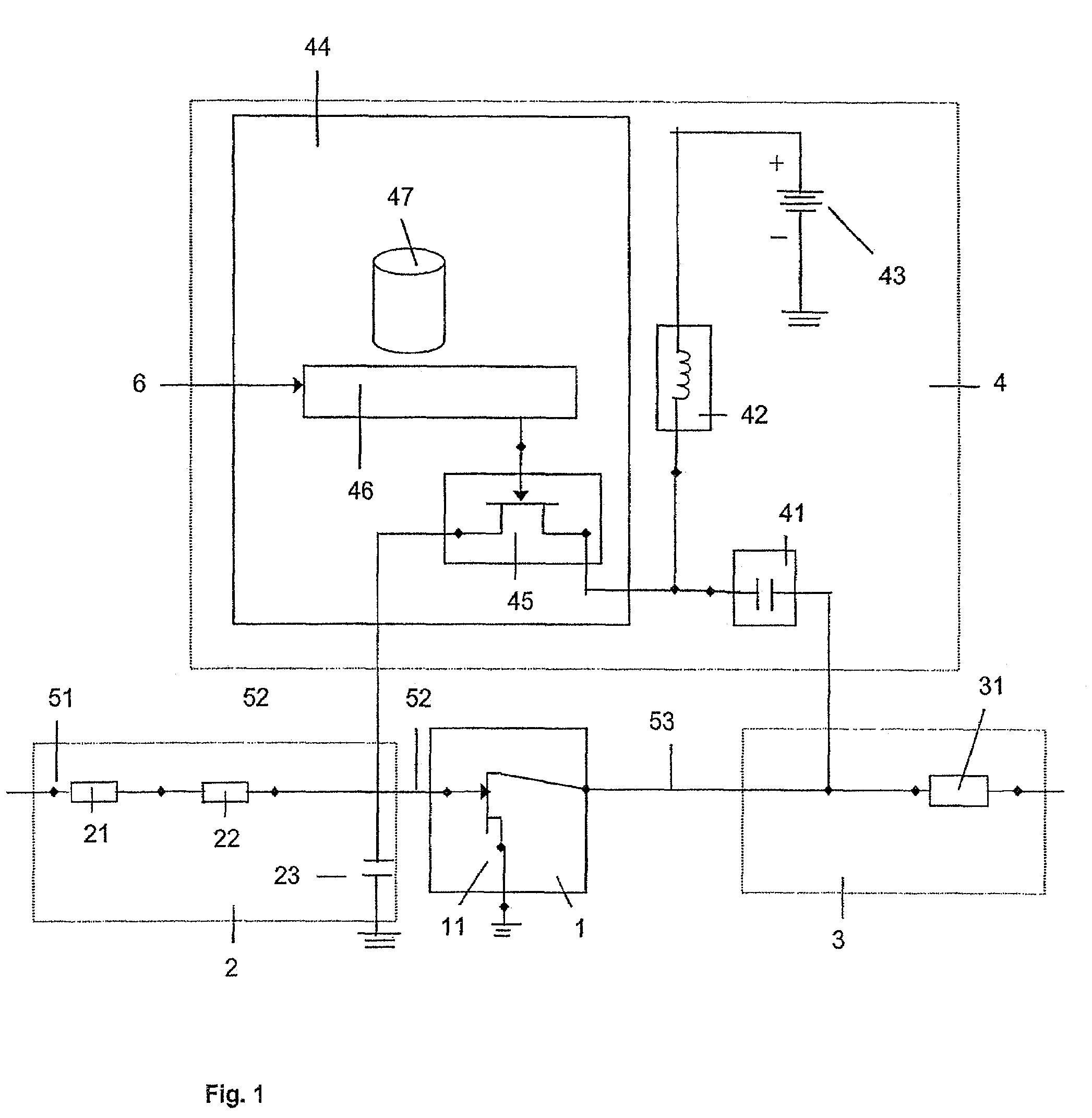
[0022]FIG. 1 shows a wideband power amplifier amplifying an electronic input signal 51, the power amplifier having an amplifier transistor stage 1, an input matching network 2, an output matching network 3 and an feedback loop 4.

[0023]The input matching network 2 and the output matching network 3 are adaptation networks adapting the input / output behavior of the power amplifier to the neighboring components of the amplification chain. For example, the input matching network comprises here two transmission lines 21 and 22 and a capacitor 23. For example, the output matching network 3 comprises here a transmission line 31.

[0024]The amplifier transistor stage 1 comprises a field-effect-transistor 11. The gate of the field-effect-transistor 11 is connected with the input matching network 2. The drain of the field-effect-transistor 11 is connected with the output matching network 3. Further, it is possible that the amplifier transistor stage 1 comprises two or more field-effect-transistor...


PUM


Abstract

The present invention relates to a power amplifier for amplifying an electronic input signal (51) and a multi-band capable frontend with such power amplifier. The power amplifier comprises an amplifier transistor stage (1) having an input (52) and an output (53) and a feedback loop (4) placed between the output (53) and the input (52) of the amplifier transistor stage (1). The feedback loop (4) comprises a capacitor (41) and a resistive element (44) in a RF path and an inductive element (42) in a DC feed path, wherein said resistive element comprises a feedback transistor (45) arranged as variable resistor within the feedback loop, and a bias control circuit (46).

Description

[0001]The invention is based on a priority application EP 04292850.7 which is hereby incorporated by reference.FIELD OF THE INVENTION[0002]The present invention relates to a power amplifier for amplifying an electronic input signal as well as a multi-band capable front-end equipped with such power amplifier.BACKGROUND OF THE INVENTION[0003]Power amplifiers are widely employed in the telecommunications industry. Telecommunication applications, such as UMTS, WiMAX, high data rate fiber transmission system or microwave systems need power amplifiers that have the ability to amplify wideband signals, e.g. spread spectrum signals in an efficient manner. Since wideband power amplifiers often show gain variations versus the used frequency range, it is difficult to provide the same output power for several frequency bands that shall be covered by the power amplifier.[0004]For example, variable attenuators are used to compensate the gain variations versus frequency.SUMMARY OF THE INVENTION[00...

Claims


Application Information

Patent Timeline
Patent Type & Authority Patents(United States)
IPC IPC(8): H03G3/30
CPCH03F1/301H03F1/306H03F1/34H03F1/48H03F3/193H03F3/1935H03G1/007H03F2200/111H03F2200/117H03F2200/141H03F2200/36
Inventor WIEGNER, DIRKMERK, THOMAS
Owner ALCATEL LUCENT SAS
Why Eureka
Try Eureka