
System and method of integrating a touchscreen within an LCD

a touchscreen and lcd technology, applied in the field of liquid crystal displays, can solve the problems of resistive touchscreens, reduce the reflection and clarity of lcds, and capacitive touchscreens can only be used with a bare finger or conductive stylus

Active Publication Date: 2008-06-17
MALIKIE INNOVATIONS LTD
View PDF22 Cites 57 Cited by
  • Summary
  • Abstract
  • Description
  • Claims
  • Application Information

AI Technical Summary

Benefits of technology

[0010]According to at least one example aspect, a touchscreen liquid crystal display that includes a liquid crystal display including a viewing surface, a liquid crystal area containing liquid crystal located behind the viewing surface, a plurality of spaced apart elongate first electrodes located on a viewing surface side of the liquid crystal area and a plurality of spaced apart elongate second electrodes located on an opposite side of the liquid crystal area, the first and second electrodes overlapping to form an array of liquid crystal pixel elements, at least some of the first electrodes being displaceable towards the second electrodes in response to external pressure applied to the viewing surface. A control circuit is connected to the first and second electrodes for controlling the operation of the liquid crystal display. The control circuit includes (i) a driver circuit for driving the electrodes for selectively controlling a display state of the pixel elements; and (ii) a measurement circuit for detecting displacement of the at least some of the first electrodes in response to external pressure applied to the viewing surface.

Problems solved by technology

Resistive touchscreens reduce the reflection and clarity of the LCD because of the added membrane layer and air gap in front of the surface of the LCD.
Capacitive touchscreens can only be used with a bare finger or conductive stylus.

Method used


Image

  • System and method of integrating a touchscreen within an LCD
  • System and method of integrating a touchscreen within an LCD
  • System and method of integrating a touchscreen within an LCD

Examples


Embodiment Construction

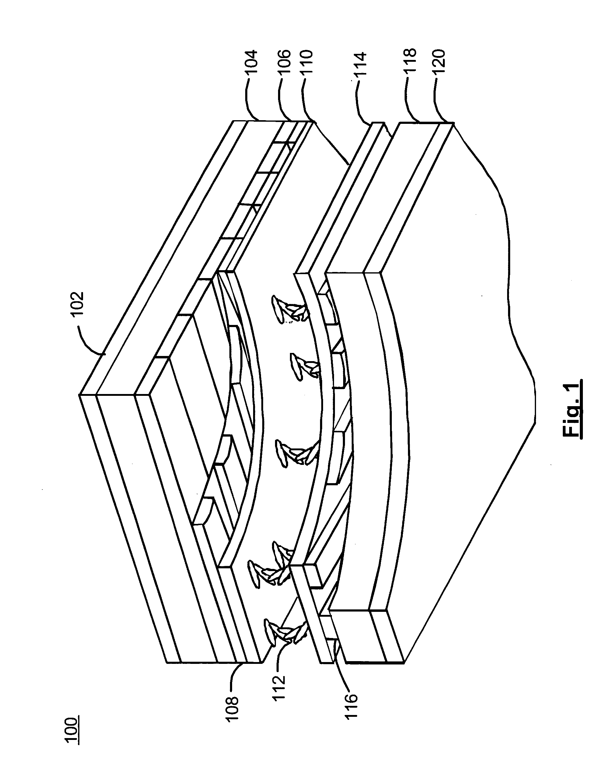
[0019]Turning now to the drawings, FIG. 1 depicts an LCD structure. As it is known in the art, the LCD 100 consists of a sandwich of liquid crystal 112 between a top glass substrate 104 and a bottom glass substrate 118 with polarizers 102, 120 on the external surfaces of the glass substrates 104, 118. A user would view information on the LCD 100 through the top glass substrate 104. The polarizers 102, 120 control the light that enters and leaves the LCD 100. The top polarizer 102 is polarized oppositely or perpendicularly to the bottom polarizer 120. Polarized light enters the LCD and twists around the liquid crystal molecules 112 so that the light's polarization becomes oppositely polarized and then exits the LCD 100. Wherever light passes through all the layers of the LCD 100, pixels appear white.

[0020]On the internal surface of the top glass substrate 104 is a colour filter 106. A first layer of strips of transparent electrodes 108 is on the top glass substrate 104. A second laye...


PUM

PropertyMeasurementUnit
dielectric constantaaaaaaaaaa
frequencyaaaaaaaaaa
pressureaaaaaaaaaa

Abstract

A touchscreen liquid crystal display that includes a liquid crystal display including a viewing surface, a liquid crystal area containing liquid crystal located behind the viewing surface, a plurality of spaced apart elongate first electrodes located on a viewing surface side of the liquid crystal area and a plurality of spaced apart elongate second electrodes located on an opposite side of the liquid crystal area, the first and second electrodes overlapping to form an array of liquid crystal pixel elements, at least some of the first electrodes being displaceable towards the second electrodes in response to external pressure applied to the viewing surface. A control circuit is connected to the first and second electrodes for controlling the operation of the liquid crystal display. The control circuit includes (i) a driver circuit for driving the electrodes for selectively controlling a display state of the pixel elements; and (ii) a measurement circuit for detecting displacement of the at least some of the first electrodes in response to external pressure applied to the viewing surface.

Description

[0001]This application claims priority to Provisional U.S. Patent Application No. 60 / 427,963 filed Nov. 21, 2002.BACKGROUND OF THE INVENTION[0002]1. Field of the Invention[0003]This invention relates to the field of liquid crystal displays (LCDs). More specifically, this invention relates to touchscreen LCDs.[0004]2. Description of the State of the Art[0005]Although there are several types of touchscreens possible, the two most commonly used touchscreens in handheld electronic devices are resistive and capacitive touchscreens.[0006]Resistive touchscreens use a thin, flexible membrane over a glass substrate. The substrate surface and the facing membrane surface have a transparent metallic coating and are separated by spacers. When a user presses on the outer surface of the membrane, the inner surface of the membrane meets the substrate causing a change in resistance at the point of contact. A touchscreen controller measures this resistance using the membrane and the substrate as a pr...

Claims


Application Information

Patent Timeline
Patent Type & Authority Patents(United States)
IPC IPC(8): G09G3/36G09G5/00G02F1/133G06F3/033G06F3/044
CPCG02F1/13306G02F1/13338G06F3/044G06F3/0445G06F3/0446
Inventor LOWLES, ROBERT J.ROBINSON, JAMES A.WU, KEN
Owner MALIKIE INNOVATIONS LTD
Features
  • Generate Ideas
  • Intellectual Property
  • Life Sciences
  • Materials
  • Tech Scout
  • Unparalleled Data Quality
  • Higher Quality Content
  • 60% Fewer Hallucinations
Learn More