
Inverted dispensing pump

a pump and pump body technology, applied in the field of pumping systems, can solve the problems of less unsightly, less accessible pump in fixed installation, and always a concern for leakage, and achieve the effect of reducing the leakage of fluid

Active Publication Date: 2008-06-24
RIEKE LLC
View PDF54 Cites 18 Cited by
  • Summary
  • Abstract
  • Description
  • Claims
  • Application Information

AI Technical Summary

Benefits of technology

"The present invention is about a fluid dispensing system that includes a pump body, inlet valve, plunger, and shipping seal to minimize leakage of fluid before use. The system also includes an intake shroud with a flow channel to draw fluid from the container into the inlet opening. Another aspect of the invention is an outlet valve to minimize dripping of fluid from the dispensing opening. The technical effects of this invention are to provide a more efficient and controlled fluid dispensing system that reduces leakage and dripping of fluid, which can be useful in various applications such as industrial cleaning, painting, and coating."

Problems solved by technology

Typically, the pump in a fixed installation is not readily accessible except by authorized personnel such that the fluid container and associated pumping mechanism are enclosed within a cabinet or docking station.
With fluid dispensing pumps, leakage is always a concern.
The mess created by the leakage is at least unsightly, and more importantly, the leakage can create hazardous conditions.
For example, leakage of liquid soap from a soap dispenser onto a floor can make the floor very slippery.
Moreover, fluid leakage is always a concern throughout the life of the pump.
If allowed to continue, the increased pressure in the pump will cause fluid to leak out the dispensing port of the pump.
The hydraulic pressure pulses created through handling can have much of the same affect upon the pump as with temperature changes described above, thereby causing leakage.
At some point the droplet will break free as a result of an external vibration and / or the inability of the fluid to withstand the higher head pressure imparted by the greater weight.
Another leakage source can be caused by the dispensing of fluid.
Left unaddressed, the vacuum inside the container can distort the container, which in turn can cause cracks in the container and subsequent leakage from the cracks.
For inverted type pumps as well as other type pumps, this arrangement limits the amount of fluid that can be evacuated from the container since the fluid can only be drawn down to the level of the intake valve, which is positioned well inside the container.
As a result, the fluid remaining in the container below the inlet valve is wasted.

Method used


Image

  • Inverted dispensing pump
  • Inverted dispensing pump
  • Inverted dispensing pump

Examples


Embodiment Construction

[0022]For the purpose of promoting an understanding of the principles of the invention, reference will now be made to the embodiments illustrated in the drawings and specific language will be used to describe the same. It will nevertheless be understood that no limitation of the scope of the invention is thereby intended. Any alterations and further modifications in the described embodiments, and any further applications of the principles of the invention as described herein are contemplated as would normally occur to one skilled in the art to which the invention relates. One embodiment of the invention is shown in great detail, although it will be apparent to those skilled in the art that some features that are not relevant to the present invention may not be shown for the sake of clarity.

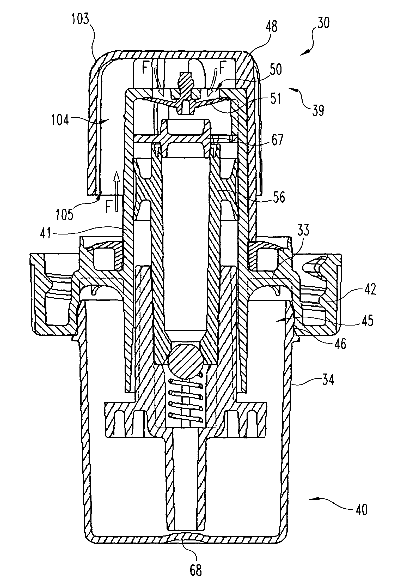
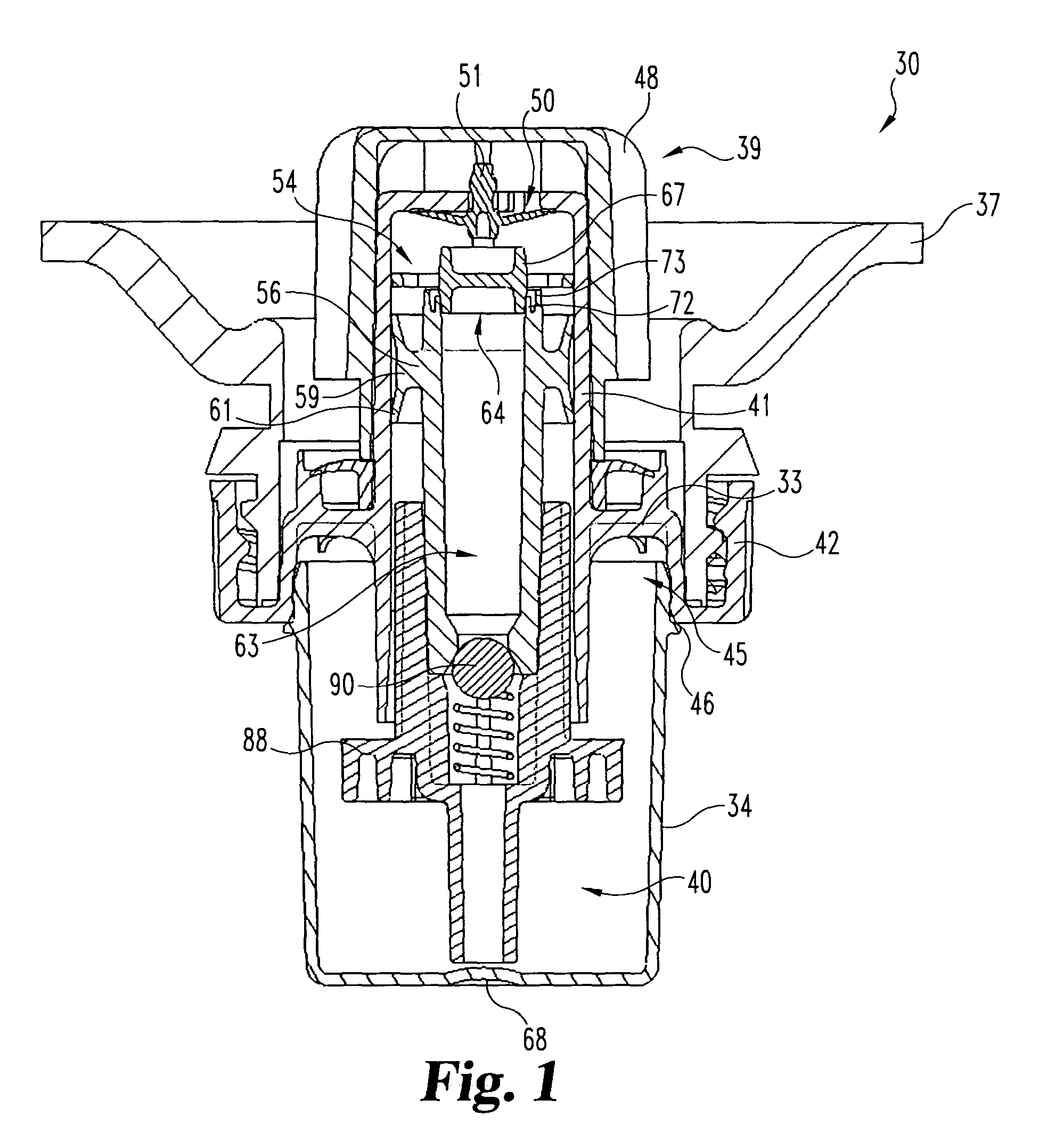
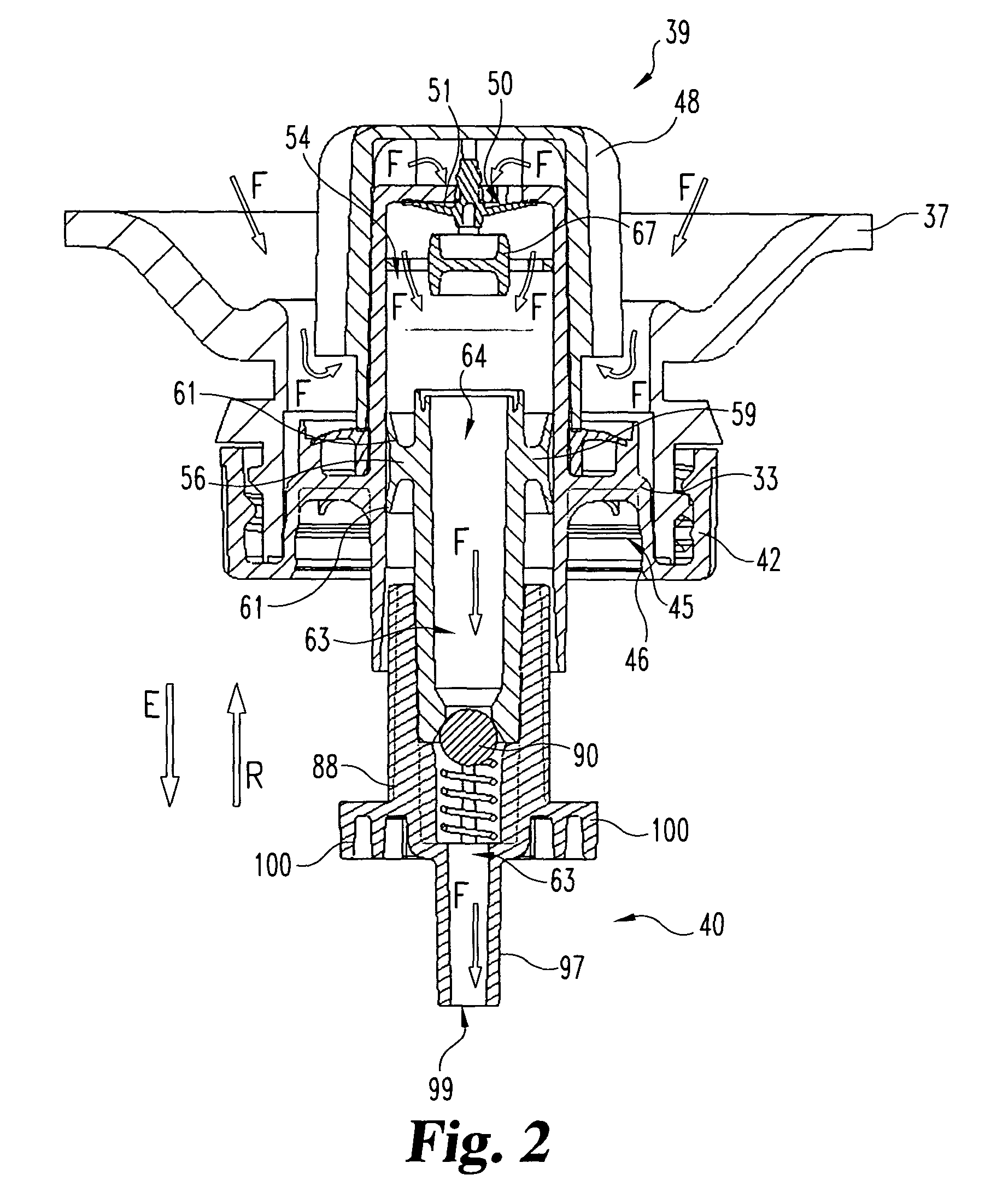
[0023]A fluid dispensing system 30 according to one embodiment, among many embodiments, is illustrated in FIG. 1. The dispensing system 30 includes a fluid pump 33 and a transit cap 34 engaged to ...


PUM


Abstract

A fluid dispensing system includes a pump body configured to couple to a container. The pump body defines fluid inlet openings and a pump cavity. A shroud cover covers the pump body to draw fluid from the container. An inlet valve allows fluid from the container to enter the pump cavity through the fluid inlet openings. A plunger is slidably received in the pump cavity, and the plunger defines a fluid passage with a dispensing opening through which the fluid is dispensed. A shipping seal seals the fluid passage during shipping to minimize leakage of the fluid during shipping. An outlet valve is disposed inside the fluid passage to minimize the height of the fluid between the outlet valve and the dispensing opening so as to minimize dripping of fluid from the dispensing opening. The pump body includes a venting structure to normalize the air pressure inside the system.

Description

BACKGROUND[0001]The present invention generally relates to fluid dispensing systems, and more specifically, but not exclusively, concerns a dispensing pump that minimizes leakage and increases of the amount of fluid that can be dispensed from a container.[0002]Fluid dispensing pumps are used in a wide variety of situations. For example, in one common situation, the fluid dispensing pump can be a manually operated pump that is used to dispense liquid hand soap in restrooms. In the case of a fixed (i.e. wall mounted) dispensing pump, aesthetics and security come into play. Typically, the pump in a fixed installation is not readily accessible except by authorized personnel such that the fluid container and associated pumping mechanism are enclosed within a cabinet or docking station. The cabinet usually has some sort of manual actuator device, such as a button or lever that can be used to manually actuate the pump and dispense the fluid. Once the fluid container is emptied, the contain...

Claims


Application Information

Patent Timeline
Patent Type & Authority Patents(United States)
IPC IPC(8): B65D88/54B05B11/00
CPCB05B11/0059B05B11/306B05B11/106
Inventor KASTING, THOMAS P.
Owner RIEKE LLC
Learn More