
Centralized memory based packet switching system and method

a packet switching and memory technology, applied in the field of data communication systems, can solve the problems of low permitted input load, architecture suffers from head-of-line blocking, and the desired output of the latter packet may go idle,

Active Publication Date: 2008-06-24
CISCO TECH INC
View PDF25 Cites 60 Cited by
  • Summary
  • Abstract
  • Description
  • Claims
  • Application Information

AI Technical Summary

Problems solved by technology

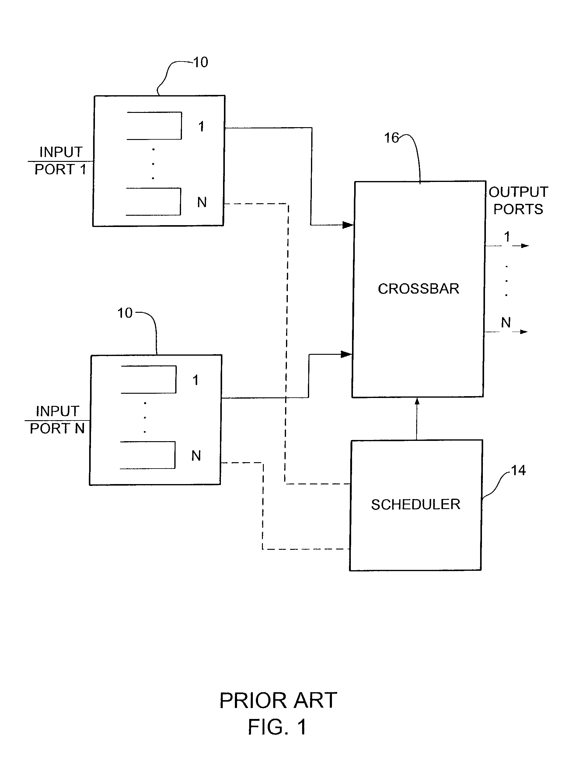
One is that this architecture suffers from head-of-line blocking.
If the desired output line of the packet at the head of the queue is under heavy contention, other packets in that queue may have to wait and the desired output of the latter packets may go idle.
Input queuing thus suffers from low permitted input load.
A drawback of virtual output queuing is that it requires a very complicated scheduler to find maximum input-output matching in order to achieve maximum throughput.
The most popular scheduling algorithms either require multiple iterations (which is impractical in high capacity switches due to the small amount of time available) to find maximum matching or find a sub-optimal matching.
However, there is no guarantee of one hundred percent throughput in the sub-optimal matching case.
Even though high throughput can be achieved for input queued switches by using a combination of virtual output queuing and complex scheduling, packets experience larger delays and delay variation in input queued switches than in output queued switches due to the input contention phenomenon.
However, if a memory cell is to contain data from two or more packets, the memory cell cannot be written into the buffer memory as soon as a packet completes.
Even off-chip, cost, space and power constraints will dictate use of DRAM rather than SRAM.
Finally, with the typical many (e.g., 8) line cards and a redundant pair of switch cards architecture, a maintenance change-over from the working switch card to the protection switch card may result in loss or duplication of all the packets stored in the buffer on the switch card.
Having a speed-up is undesirable as it requires a high bandwidth switch core but offers a smaller revenue generating bandwidth.
Traditional buffer and queue management does not allow packing multiple packets into a single memory cell.
This results in two limitations.
The first limitation is the efficiency of memory utilization.
Due to the complexity of the scheduler design, almost all conventional switch designs require fix-sized data cells being switched.

Method used


Image

  • Centralized memory based packet switching system and method
  • Centralized memory based packet switching system and method
  • Centralized memory based packet switching system and method

Examples


Embodiment Construction

[0037]The following description is presented to enable one of ordinary skill in the art to make and use the invention. Descriptions of specific embodiments and applications are provided only as examples and various modifications will be readily apparent to those skilled in the art. The general principles described herein may be applied to other embodiments and applications without departing from the scope of the invention. Thus, the present invention is not to be limited to the embodiments shown, but is to be accorded the widest scope consistent with the principles and features described herein. For purpose of clarity, details relating to technical material that is known in the technical fields related to the invention have not been described in detail.

[0038]The present invention operates in the context of a data communication network including multiple nodes. Nodes of a network may be user workstations, servers, routers, etc. Some of the nodes in a network that employs the present ...


PUM


Abstract

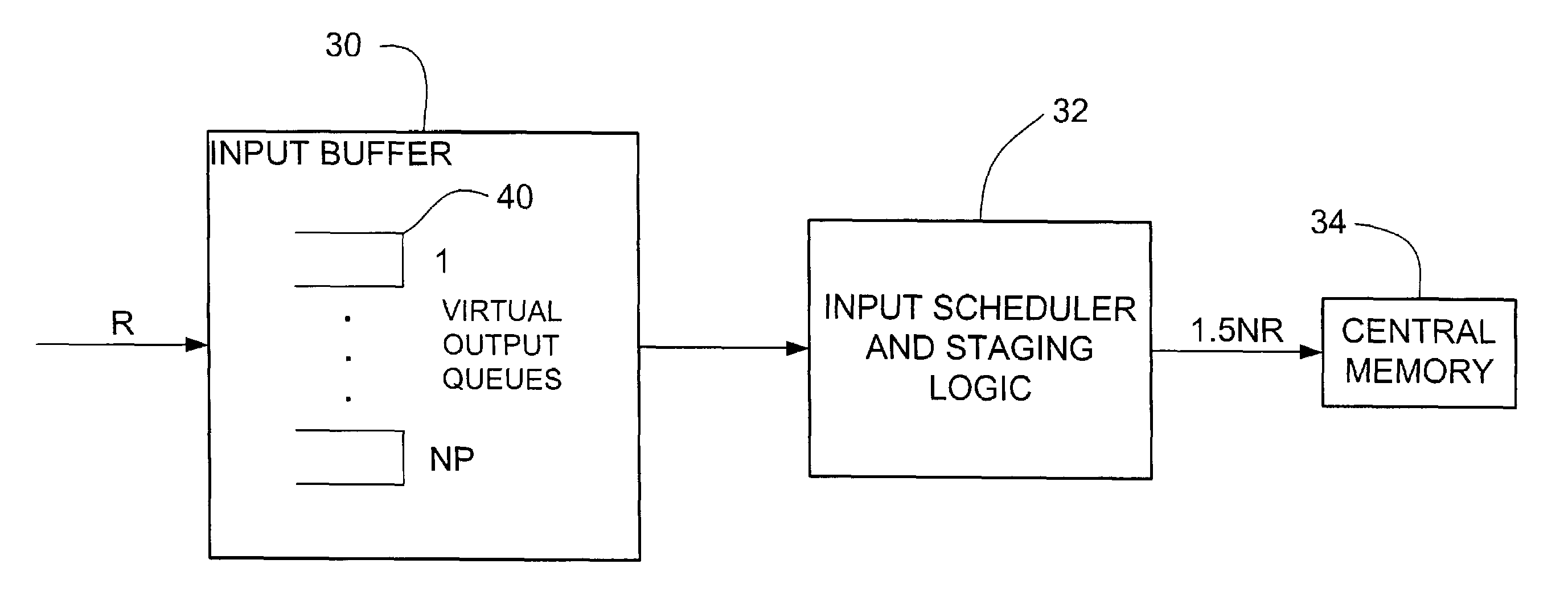
A packet switching system and method are disclosed. The system includes a plurality of input and output ports and an input buffer at each of the input ports. The system further includes an input scheduler associated with each of the input buffers and a centralized memory shared by the output ports. An output buffer is located at each of the output ports and an output scheduler is associated with each of the output ports. Each of the input buffers comprises a plurality of virtual output queues configured to store a plurality of packets in a packed arrangement.

Description

BACKGROUND OF THE INVENTION[0001]The present invention relates generally to data communications systems, and more specifically, to a centralized memory based packet switching system and method.[0002]The interconnection of networks relies on implementation of real-time packet switching fabrics. Switches are used to route arriving packets on the basis of information contained in each packet header. The switch functions to route packets to their correct destination port and resolve conflicts when several simultaneously arriving packets are headed to a common output port. Queuing is required to prevent packets from being lost whenever another packet simultaneously arrives on a different input and is bound for the same output.[0003]A switch may employ input buffers and / or output buffers. Input buffers connect to input lines and output buffers connect to output lines. A fabric interconnects the input and output buffers. The fabric itself may be buffered or buffer-less. A buffer-less fabri...

Claims


Application Information

Patent Timeline
IPC IPC(8): H04L12/28H04L12/54
CPCH04L49/101H04L49/3027H04L49/3045
Inventor PRASAD, SHARATSEAVER, TERRYWANG, YANFENGDENG, YUHERNANDEZ, LUIS M.
Owner CISCO TECH INC
Learn More