Optical apparatus

a technology of optical equipment and optical axis, which is applied in the field of optical equipment, can solve the problems of user inability to determine the focusing direction, the user's video image becomes unsightly, and the contrast is very low, and achieves the effect of more stable configuration and high accuracy

Inactive Publication Date: 2008-07-01
CANON KK
View PDF5 Cites 0 Cited by
  • Summary
  • Abstract
  • Description
  • Claims
  • Application Information

AI Technical Summary

Benefits of technology

[0011]The present invention is directed to an optical apparatus including a focus detection sensor, having a more stabilized configuration, and can implement auto focusing with high accuracy without interfering with a user handling an operation ring.

Problems solved by technology

However, in the case where the degree of blurring is high, it is necessary for a user to determine an in-focus position only after moving the focusing lens up to an end of a focusing lens movable range.
Thus, the video image becomes unsightly for the user.
Thus, in a significantly defocused state, the contrast is very low, and a user cannot determine a focusing direction.
During this operation, the user is required to watch unfocused images, which causes the user to feel uncomfortable.
In a conventional method, it is difficult to mount a lens hood on an optical apparatus with high accuracy because a focus detection sensor module is disposed inside a lens hood.
Thus, it is difficult to align a range-finding area with a shooting area with high accuracy.
Thus, in a conventional method, the configuration of the apparatus becomes complicated and it is difficult to stably perform an auto focus (AF) function.

Method used


Image

  • Optical apparatus
  • Optical apparatus
  • Optical apparatus

Examples


Embodiment Construction

[0018]Various exemplary embodiments, features, and aspects of the present invention will now herein be described in detail with reference to the drawings. It is to be noted that the relative arrangement of the components, the numerical expressions, and numerical values set forth in these embodiments are not intended to limit the scope of the present invention unless it is specifically stated otherwise.

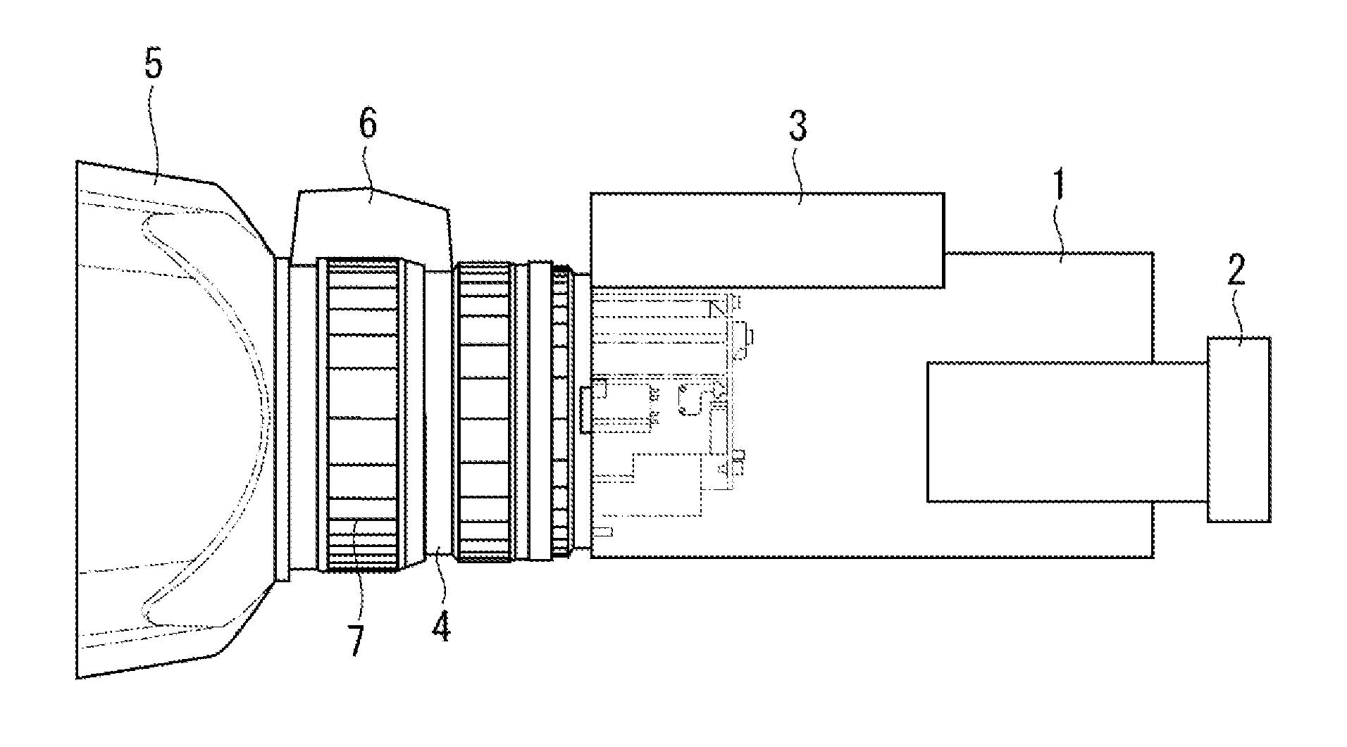
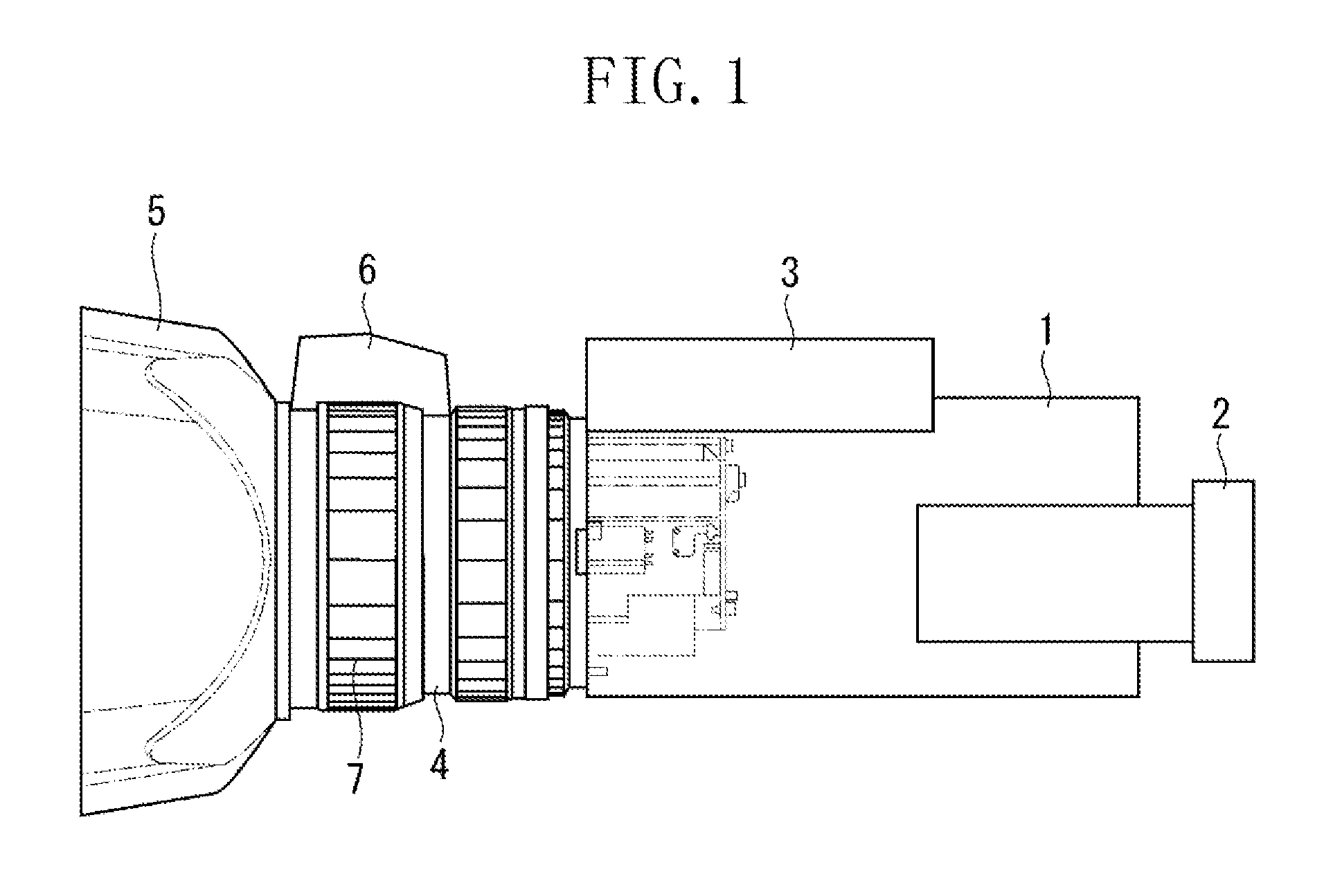
[0019]Now, an exemplary embodiment of the present invention will be described below. FIG. 1 illustrates a configuration of a video camera that is an optical apparatus according to the present exemplary embodiment. Referring to FIG. 1, the video camera according to the present exemplary embodiment includes a camera body 1, a viewfinder 2, and a grip 3. The viewfinder 2 is disposed in an upper rear portion of the camera body 1. The grip 3 is disposed in a right portion of the camera body 1 from the viewfinder 2 so that a user can stably grip the camera body 1.

[0020]Furthermore, the video...


PUM


Abstract

An optical apparatus having a grip for gripping a camera body. The apparatus includes a lens element, a lens barrel configured to retain the lens element, a focus detection sensor disposed on an outer peripheral portion of the lens barrel, and a ring-shaped operation member configured to manually adjust at least focusing or zooming. The focus detection sensor is disposed on an outside of the ring-shaped operation member and on a same side as the grip of the camera body with respect to an optical axis of the lens element.

Description

BACKGROUND OF THE INVENTION[0001]1. Field of the Invention[0002]The present invention relates to an optical apparatus such as a digital camera, a video camera, a digital still camera, a television camera, and an interchangeable lens including a focus detection sensor for automatically focusing on an object.[0003]2. Description of the Related Art[0004]With a television auto focusing (TVAF) function in a video camera and a television camera, a video signal from an image sensor such as a charge-coupled device (CCD) is captured while a focusing lens is moved in a small amount to determine a focusing direction according to the difference in contrast values obtained before and after moving the focusing lens.[0005]In such a TVAF system, when a focusing lens is disposed at a position close to an in-focus position, the focusing lens can immediately enter an in-focus state. However, in the case where the degree of blurring is high, it is necessary for a user to determine an in-focus position ...

Claims


Application Information

Patent Timeline
Patent Type & Authority Patents(United States)
IPC IPC(8): G02B7/02
CPCG02B7/08
Inventor OKADA, TADANORI
Owner CANON KK
Why Eureka
Try Eureka