Method for selectively irradiating a material layer, production method, and computer program product

Pending Publication Date: 2021-03-18
SIEMENS ENERGY GLOBAL GMBH & CO KG
View PDF0 Cites 2 Cited by
  • Summary
  • Abstract
  • Description
  • Claims
  • Application Information

AI Technical Summary

Benefits of technology

[0017]It is therefore an object of the present invention to provide means which avoid the aforementioned overheating in the process and can therefore lead to a

Problems solved by technology

One problem which occurs more greatly because of this situation is local overheating, which is caused by irradiation vectors (scan vectors) that are too short.
The reason why the overheating occurs precisely during production because of irradiation vectors that are too short in length is that in a particular surface region, the energy beam passes several times over the same or adjacent surface regions in a short time, and the heat is possibly never dissipated sufficiently from this region.
In other words, the radiation power or energy density (per unit time) which is introduced by the energy beam into the powder bed during the irradia

Method used


Image

  • Method for selectively irradiating a material layer, production method, and computer program product
  • Method for selectively irradiating a material layer, production method, and computer program product
  • Method for selectively irradiating a material layer, production method, and computer program product

Examples


Embodiment Construction

[0048]In the exemplary embodiments and figures, elements which are the same or have the same effect may respectively be provided with the same references. The elements represented and their size proportions with respect to one another are not in principle to be regarded as true to scale; rather, individual elements may be represented exaggeratedly thick or largely dimensioned for better representability and / or for better comprehensibility.

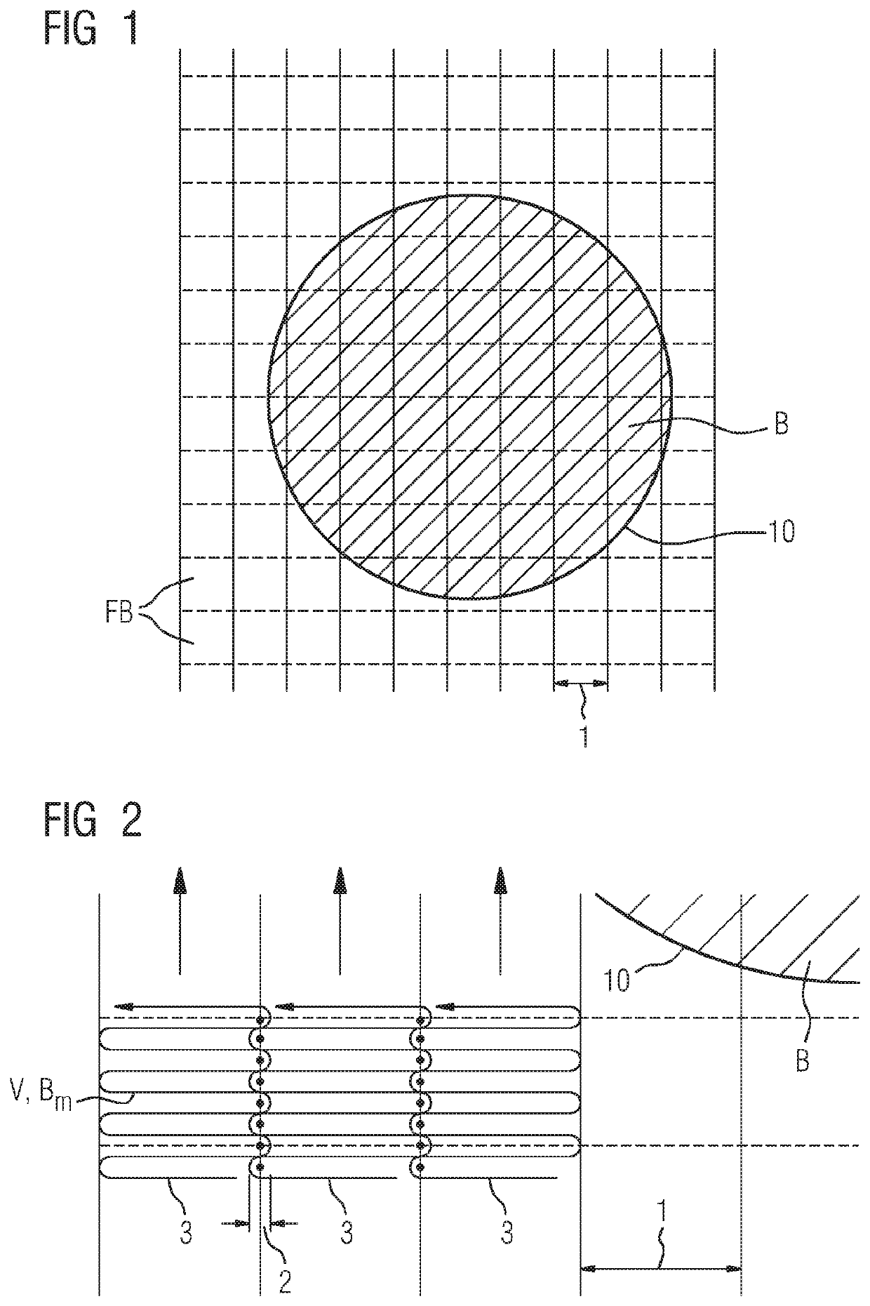
[0049]FIG. 1 shows a component, or a part thereof, in a plan view. The component, or a design model (CAD file) of the component, is denoted by the reference B. The part of the component B represented as being round may furthermore denote a cross-sectional view of the component—for example during its additive production, or of a modeled layer thereof.

[0050]The component is advantageously a component which is used in the hot-gas path of a turbomachine, for example of a gas turbine. In particular, the component may be a rotor blade or guide vane, a se...


PUM

PropertyMeasurementUnit
Fractionaaaaaaaaaa
Lengthaaaaaaaaaa

Abstract

A method for selectively irradiating a material layer in additive manufacturing, the method includes: providing a predetermined component geometry which contains geometrical information of individual layers of a component to be manufactured additively; and defining layer by layer an irradiation pattern in areas of a layer to be constructed for the manufacturing of the component, the irradiation pattern comprising irradiation vectors in each area; and, if a predefined irradiation vector length is not reached in a first area, lengthening irradiation vectors in a second area of the layer adjacent to the first area as far as a component contour.

Description

CROSS REFERENCE TO RELATED APPLICATIONS[0001]This application is the U.S. National Stage of International Application No. PCT / EP2019 / 050309 filed 8 Jan. 2019, and claims the benefit thereof. The International Application claims the benefit of European Application No. EP18155290 filed 6 Feb. 2018. All of the applications are incorporated by reference herein in their entirety.FIELD OF INVENTION[0002]The present invention relates to a method for selectively irradiating a material layer in additive production, to a corresponding additive production method, to a component produced with this production method, and to a corresponding computer program product.[0003]The selective irradiation method may constitute or comprise a CAM (computer-aided manufacturing) method.[0004]The component advantageously denotes a component intended for use in a turbomachine, advantageously in the hot-gas path of a gas turbine. Correspondingly, the component advantageously consists of or comprises a nickel-bas...

Claims


Application Information

Patent Timeline
IPC IPC(8): F01D5/28B22F3/105B22F5/04B33Y50/02
CPCF01D5/28B22F3/1055B33Y10/00B33Y50/02B22F5/04B22F5/009C22C1/0433B33Y80/00B29C64/393Y02P10/25B22F10/28B22F10/366B33Y70/00B22F10/00B22F2203/11B22F2301/15F05D2230/31F05D2300/172F05D2300/175
Inventor GEISEN, OLE
Owner SIEMENS ENERGY GLOBAL GMBH & CO KG
Why Eureka
Try Eureka