Injection moulding machine having a coating installation

a technology of injection moulding machine and coating, which is applied in the direction of coatings, etc., can solve the problems of unsatisfactory results in this respect, unsatisfactory dosing accuracy, and quality problems in the finished coated part, so as to improve the dosing behaviour of the rim coating installation and improve the quality of the componen

Active Publication Date: 2021-06-01
KRAUSSMAFFEI TECH GMBH
View PDF22 Cites 0 Cited by
  • Summary
  • Abstract
  • Description
  • Claims
  • Application Information

AI Technical Summary

Benefits of technology

[0006]It is therefore an object of the invention to indicate an injection moulding machine having a coating installation, in particular a RIM coating installation, with which a distinctly improved dosing behaviour of the RIM coating installation is able to be achieved, and therefore an improved component quality if able to be obtained.
[0011]Therefore a splitting of the coating installation takes place into a low pressure part (NDT) and a high pressure part (HDT). According to the invention, it was found that coating installations which in the prior art are usually constructed in a compact and highly integrated manner and are housed on a pallet, which contain storage containers, low pressure feed pumps and high pressure pumps, are to be separated to increase the quality of the injection moulded parts. It is proposed according to the invention, also contrary to the usual professional method of procedure, namely to keep the moved mass of the movable platen as small as possible in order to save cycle times, to in fact couple the high pressure pumps, which are distinctly larger and heavier with regard to their overall size compared to the low pressure feed pumps of a coating installation, to the movable platen so as to be jointly movable. For this, usually a mechanical connection on a tray comes into consideration, which tray is connected on the rear side of the movable platen with the latter and if applicable has a separate support with respect to the machine bed. The core of the invention is therefore to mechanically couple the entire high pressure conducting or high pressure generating means of the coating installation to the movable platen or at least to the platen on which a tool cavity is arranged, which is suitable for the coating of an injection moulded blank. Such an arrangement of all high pressure conducting components, therefore all components which either generate or conduct the second pressure level p2, on a movable platen has, in addition, the advantage that connecting lines between the high pressure pumps and the filters or respectively between filters and the mixing head can be constructed so as to be completely or at least predominantly rigidly piped, i.e. can be formed with rigid pipelines, e.g. made of steel.
[0012]Depending on the arrangement and construction of the mixing head, it may be necessary to provide a bulkhead plate in the immediate vicinity of the mixing head, up to which bulkhead a rigid piping can lead. Starting from the bulkhead plate, it may be necessary to bridge a relatively short distance by means of flexible high pressure hoses. The length of these high pressure hoses must, however, only be dimensioned to be so great that a dismantling of the mixing head from the mould tool half is possible for maintenance purposes. Depending on whether the mixing head has to be moved in a particular direction for maintenance purposes, it can also be successful, through suitable selection of the high pressure connections on the mixing head, to configure the rigid piping up to the mixing head and therefore to further increase the dosing accuracy.
[0015]Such injection moulding machines can be converted in a simple manner by the dismantling of one of the available thermoplastics injection units and can offer corresponding installation space for components of the coating installation.
[0019]Expediently, a free line length is formed by means of rigid pipes between high pressure pumps and / or filters and the mixing head at least except for flexible hoses necessary for maintenance purposes. The rigid pipes have the advantage here that smaller expansions take place e.g. with high pressure injecting occurring in a pulse-like manner, and therefore during the injecting of the components into a coating cavity, the predetermined and pre-selected dosing quantities of the coating material can be maintained more precisely. Hereby, the quantity of material of the coating material which is injected is made more precisely reproducibly repeatable, so that an increase in quality for the produced components with the injection moulding machine according to the invention is able to be realized.
[0025]It is therefore successful, with a sufficiently dimensioned low pressure part, to supply several injection moulding machines or respectively their high pressure parts of the coating installation with one and the same batch of the coating components from a common low pressure part.

Problems solved by technology

In individual cases it was found that e.g. in the case of particularly small injection weights of the reaction components with such an arrangement of the RIM coating installation, unsatisfactory results are obtained in this respect.
In individual cases, such a machine layout leads to unsatisfactory dosing accuracies and therefore to quality problems in the finished coated part.

Method used


Image

  • Injection moulding machine having a coating installation
  • Injection moulding machine having a coating installation
  • Injection moulding machine having a coating installation

Examples


first embodiment

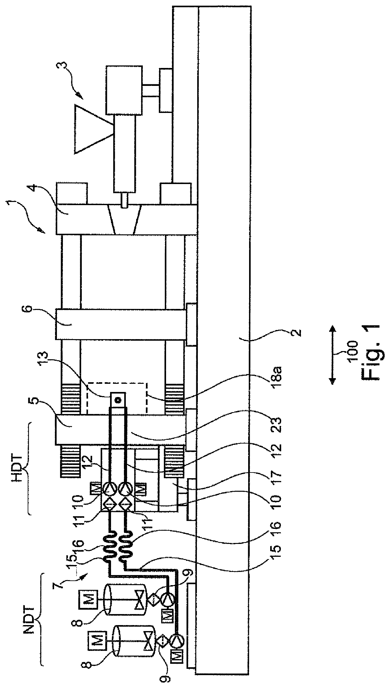
[0040]FIG. 1 shows first embodiment of an injection moulding machine 1 according to the invention. An injection unit 3 is arranged in a known manner on a machine bed 2 and cooperates with a fixed platen 4. The injection moulding machine according to FIG. 1 is configured as a three-plate injection moulding machine and has, in addition, a movable platen 5 and a reversing plate unit 6.

[0041]Furthermore, the injection moulding machine 1 according to the invention in accordance with FIG. 1 has a coating installation 7. The coating installation 7 has a low pressure part NDT and a high pressure part HDT. Associated with the low pressure part NDT are storage containers 8 for coating components and feed pumps 9 for the transport of the coating components at a first relatively low pressure level p1.

[0042]In the embodiment according to FIG. 1, the low pressure part NDT is arranged on a lengthened machine bed 2 lying opposite the injection unit 3.

[0043]The high pressure part HDT has high pressu...


PUM

PropertyMeasurementUnit
pressureaaaaaaaaaa
lengthaaaaaaaaaa
weightsaaaaaaaaaa

Abstract

The invention relates to an injection moulding machine having a coating installation, wherein the injection moulding machine has at least one fixed platen and one movable platen for the fastening of mould tool halves of at least one mould tool, and the coating installation has first pressure-generating and / or first pressure-conducting means for coating components at a first, relatively low pressure level and second pressure-generating and / or second pressure-conducting means for the coating components at a second, relatively high pressure level, wherein at least all second pressure-generating and all second pressure-conducting means are coupled to the movable platen so as to be jointly movable along a movement path of the movable platen.

Description

CROSS-REFERENCES TO RELATED APPLICATIONS[0001]This application is the U.S. National Stage of International Application No. PCT / EP2016 / 073714, filed Oct. 5, 2016, which designated the United States and has been published as International Publication No. WO 2017 / 063922 and which claims the priority of German Patent Application, Serial No. 10 2015 117 309.3, filed Oct. 12, 2015, pursuant to 35 U.S.C. 119(a)-(d).BACKGROUND OF THE INVENTION[0002]The invention relates to an injection moulding machine having a coating installation for the production of coated injection moulded parts.[0003]A generic injection moulding machine having a coating installation, e.g. a RIM installation, is known from EP 1 993 802 B1 or from its German patent application DE 10 2006 009 900 A1 laid open to public inspection, giving rise to a right of priority. A RIM coating installation is understood to mean a reaction injection moulding installation (RIM installation), in which a two-component reactive mixture is ...

Claims


Application Information

Patent Timeline
Patent Type & Authority Patents(United States)
IPC IPC(8): B29C45/14B29C37/00B29C45/16B29C67/24B29B7/74B29B7/86B29K75/00B29C45/03
CPCB29C37/0028B29B7/7457B29B7/86B29C45/14B29C45/16B29C45/1628B29C45/1679B29C67/246B29C2037/0035B29C2045/033B29C2045/1632B29C2045/1685B29K2075/00
Inventor SCHNEEBAUER, MARTINEILHARDT, FLORIANKLOTZ, BERNDDYKHUIS, MATTHIAS
Owner KRAUSSMAFFEI TECH GMBH
Why Eureka
Try Eureka