
Fabricated abutment structure for wharf engineering and use method of fabricated abutment structure

A prefabricated and pier technology, which is applied in the direction of basic structure engineering, pier, quay wall, etc., can solve the problems of difficult prefabricated pier lifting and installation, continuous laying of steel bars is impossible, and the plane scale of pier is large, so as to improve the accuracy and construction safety, superior construction convenience, and accelerated construction progress

Pending Publication Date: 2022-07-22
CCCC THIRD HARBOR CONSULTANTS
View PDF2 Cites 0 Cited by
  • Summary
  • Abstract
  • Description
  • Claims
  • Application Information

AI Technical Summary

Problems solved by technology

[0006] Although the above-mentioned patents give the technical method of using prefabricated piers, there are also related key technical issues that need to be overcome, mainly including: (1) The piers of the wharf project need to bear huge ship loads, and the lower part of the pile foundation The number is large, and the plane scale of the piers is generally large. It is difficult for the general crane ship equipment to lift and install the prefabricated piers. Therefore, it should be disassembled and the piers should be divided into multiple modules according to the actual use requirements and lifting capacity. Respectively prefabricated and installed; (2) The conventional cast-in-place piers are equipped with steel bars in all directions up, down, left, and right, and the concrete is poured continuously on the plane, so that when the entire pier is partially stressed, the rest of the pier is transmitted through the interior of the pier. Participate in bearing the load together and transfer the load to all the pile foundations. However, after the pier abutment is modularized and prefabricated separately, it is impossible to realize the continuous laying of steel bars, so innovative means should be used to connect multiple modules; (3) The steel pipe piles of conventional cast-in-place piers extend into the cast-in-place piers, and the upper and lower parts are reliably connected through the pile core reinforcement cage and pile core concrete. Generally, it can only be connected by grouting after the reserved pile holes, limited by the size of the reserved pile holes, the pile foundation needs to be connected and strengthened with prefabricated piers by innovative means; Avoid the process of pile core structure

Method used


Image

  • Fabricated abutment structure for wharf engineering and use method of fabricated abutment structure
  • Fabricated abutment structure for wharf engineering and use method of fabricated abutment structure
  • Fabricated abutment structure for wharf engineering and use method of fabricated abutment structure

Examples


Embodiment 1

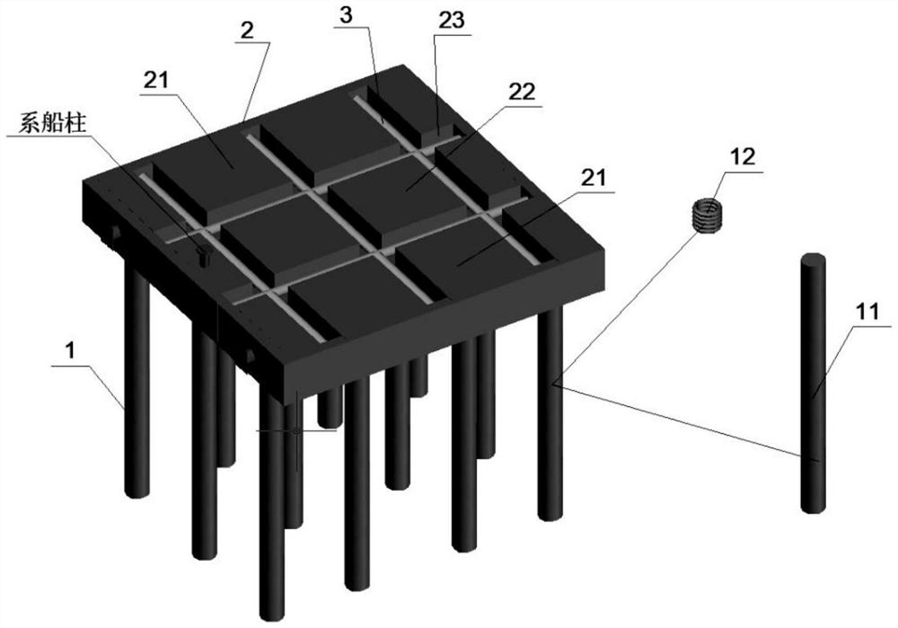
[0059] This embodiment mainly introduces the design of a prefabricated pier structure for wharf engineering; please refer to the specific structure figure 1 , figure 1 The overall installation diagram of the prefabricated abutment provided by the present invention.

[0060] A prefabricated pier structure for wharf engineering, comprising a pile foundation 1, a slotted modular pier 2, a connecting steel frame 3, and ancillary facilities;

[0061] The pile foundation 1 is connected with the lower end of the slotted modular abutment 2;

[0062] The connecting steel frame 3 is located in the slot 23 at the upper end of the slotted modular abutment 2;

[0063] The auxiliary facilities are prefabricated on the slotted modular abutment 2 .

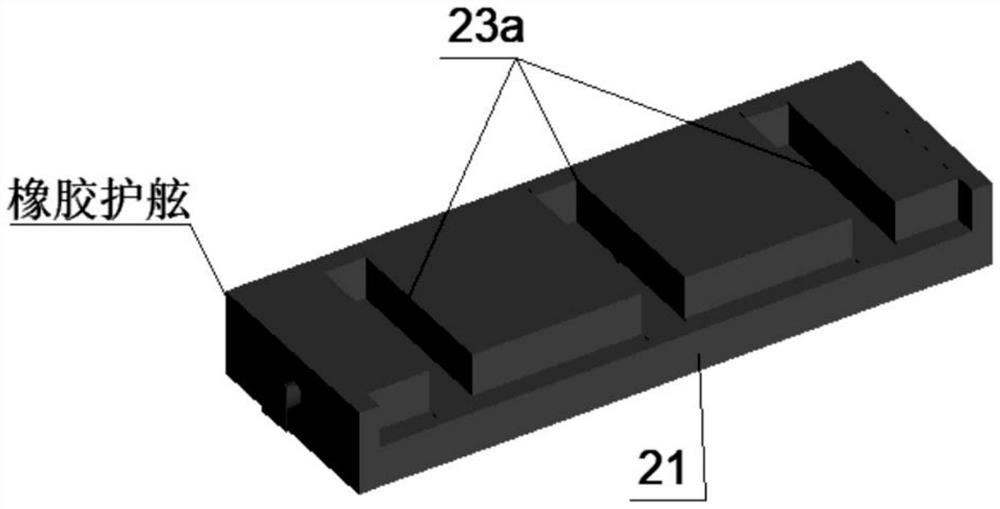
[0064] Further, the slotted modular abutment 2 includes a ship docking module 21 and a mooring module 22; please refer to the specific structures of the ship docking module 21 and the mooring module 22 image 3 and Figure 4 ; image 3 The ...

Embodiment 2

[0082] Based on the above Embodiment 1, this embodiment mainly introduces an optimal design of a prefabricated pier structure for wharf engineering.

[0083] A prefabricated pier structure for wharf engineering includes: pile foundation 1, slotted modular pier 2, connecting steel frame 3, and auxiliary facilities.

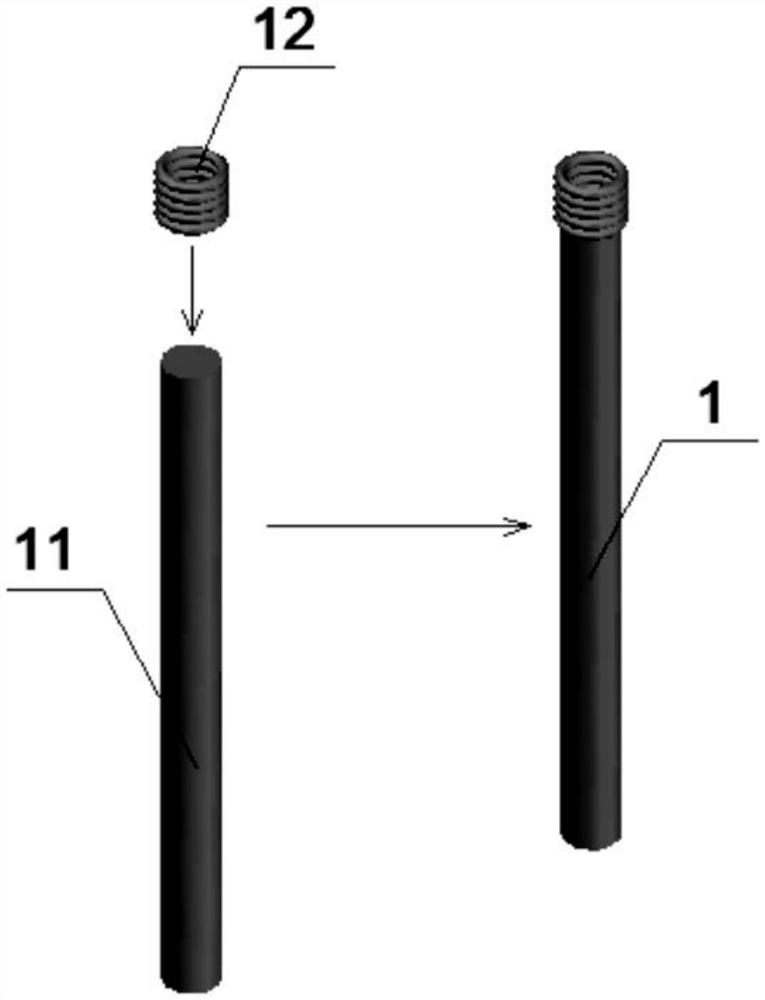
[0084] As a preferred technical solution of the present invention, the pile foundation 1 is composed of a steel pipe pile 11 and a corrugated steel pipe 12 . The slotted modular pier 2 can be divided into a ship-berthing module 21 and a mooring module 22 according to actual needs and construction lifting capacity. The slotted modular abutment 2 is internally provided with a slot 23 and a reserved pile hole 24 .

[0085] As a preferred technical solution of the present invention: after the pile driving is completed, the ship-receiving module 21 and the mooring module 22 are respectively hoisted on the upper part of the pile foundation 1, and the corrugated steel pi...

Embodiment 3

[0099] Based on the above-mentioned embodiments 1-2, this embodiment mainly introduces a method for using a prefabricated pier structure for wharf engineering, which includes the following steps:

[0100] S1, prepare the pile foundation 1, and connect the steel pipe pile 11 and the corrugated steel pipe 12 into one body;

[0101] S2. Use piling ship to sink piles;

[0102] S3. Prefabricate the ship docking module 21 and the mooring module 22, and simultaneously install the auxiliary facilities in place at one time;

[0103] S4, hoist the ship-berthing module 21 and the mooring module 22 on the upper part of the pile foundation 1, and the reserved pile holes 24 are directly supported on the top surface of the pile foundation 1;

[0104] S5. Connect the pile foundation 1 with the ship-berthing module 21 and the mooring module 22 to form a whole by grouting, and the bottom formwork can adopt a simple hanging formwork process;

[0105] S6, hoist the connecting steel frame 3 into...


PUM


Abstract

The invention discloses an assembly type abutment structure for wharf engineering and a using method of the assembly type abutment structure. The assembly type abutment structure structurally comprises pile foundations, slotting type modular abutments, connecting steel frames and subsidiary facilities. The pile foundation is connected with the lower end of the slotted modular abutment, the connecting steel frame is located in a notch in the upper end of the slotted modular abutment, and the subsidiary facility is prefabricated on the slotted modular abutment; the slotted modular abutment comprises a berthing module and a mooring module, the notches are located at the joint of the berthing module and the mooring module, each notch is composed of a berthing module prefabricated notch and a mooring module prefabricated notch, and the notches are evenly distributed in the slotted modular abutment; the pile foundation comprises a steel pipe pile and a corrugated steel pipe, and the corrugated steel pipe is welded to the top of the steel pipe pile. Different modules are connected into a whole through the connecting steel frames and the notch post-cast strips, the integrity and the force transmission effectiveness of the abutment structure are ensured, and the component quality and the construction progress are improved through the prefabrication mode.

Description

technical field [0001] The invention belongs to the field of building structural component design, in particular to a prefabricated pier structure for wharf engineering and a method for using the same. Background technique [0002] The conventional pier and abutment structures of wharf projects mainly include prefabricated pile foundations and cast-in-place piers, but there are a lot of problems with conventional piers, such as: (1) The upper piers are made of large-volume cast-in-place concrete; Relying on the pile foundation to build the fence system, erecting the integral bottom form and side form for pouring, it takes a long time, and the measures such as load-bearing hoop, wood, formwork and other measures are expensive; It is necessary to wait for the tide level during construction and the splash zone, and the construction window period is limited, and the newly poured concrete has the risk of being submerged by the tide; (3) The large-volume piers involve layered pour...

Claims


Application Information

Patent Timeline
IPC IPC(8): E02B3/06E02D27/12E02D5/28E02B3/24E02B3/26
CPCE02B3/068E02D27/12E02D5/285E02B3/24E02B3/26
Inventor 崔磊李武陈海峰吴辉
Owner CCCC THIRD HARBOR CONSULTANTS
Learn More