Packet scheduling system and method for high-speed packet networks

a packet network and packet scheduling technology, applied in data switching networks, frequency-division multiplexes, instruments, etc., can solve problems such as improving complexity, difficult to implement algorithms in high-speed network environments, and inability to implement systems

Inactive Publication Date: 2008-07-01
ELECTRONICS & TELECOMM RES INST
View PDF13 Cites 6 Cited by
  • Summary
  • Abstract
  • Description
  • Claims
  • Application Information

AI Technical Summary

Benefits of technology

[0012]The present invention provides a packet scheduling system and method by which the delay bound and fairness index of the WFQ level can be guaranteed in a switch or a router in a high-speed packet exchange network and the calculation complexity O(1) of the system virtual time can be maintained.

Problems solved by technology

However, since the minimum unit of traffic is a packet in an actual packet network environment and a server can transmit only one packet at a time, it is impossible to actually implement the system suggested in the article and the article is only providing conceptual performance criteria which all process scheduling algorithms aim at.
Accordingly, it is actually difficult to implement the algorithm in a high-speed network environment requiring high-speed determination of transmission order of packets.
Thus, the SCFQ algorithm improves the complexity due to calculation of the virtual time but degrades the delay bound that can be guaranteed, compared to the WFQ algorithm.
The SPFQ algorithm has an advantage of maintaining good performance but has a disadvantage of an arrangement process for the virtual start time which is additionally needed.
However, this algorithm has a disadvantage of overhead for continuously collecting and managing information on packets waiting in a queue at a time when the system virtual time is calculated.

Method used


Image

  • Packet scheduling system and method for high-speed packet networks
  • Packet scheduling system and method for high-speed packet networks
  • Packet scheduling system and method for high-speed packet networks

Examples


Embodiment Construction

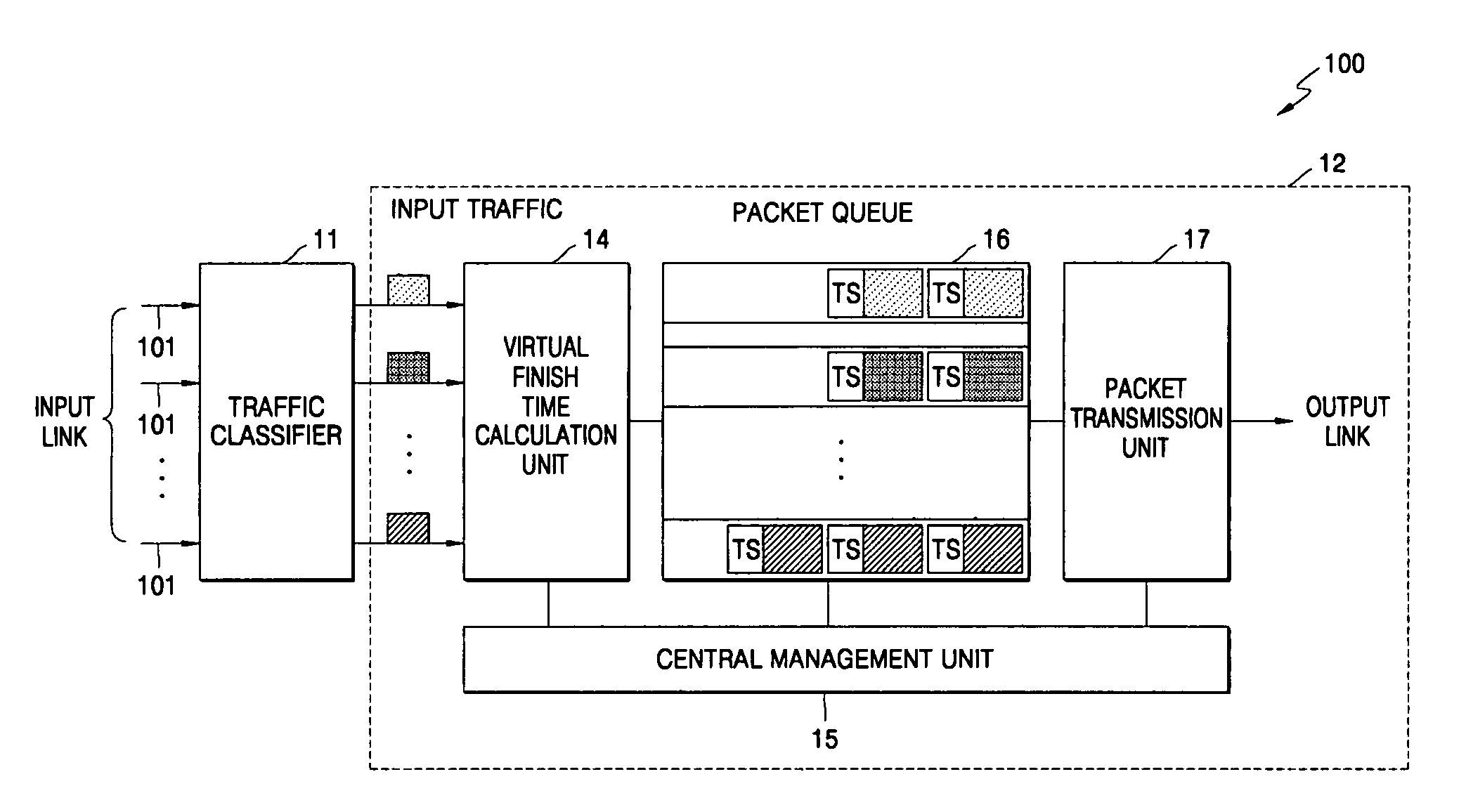
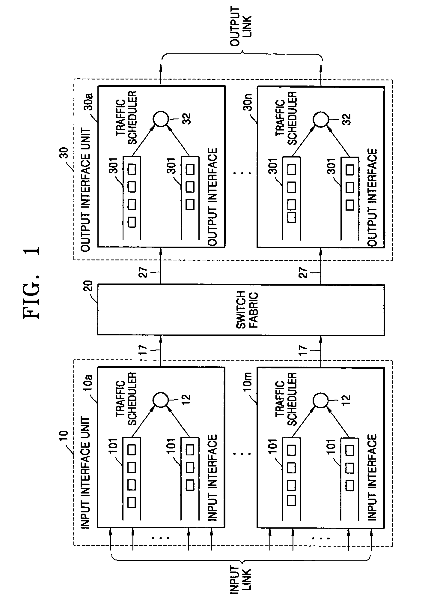
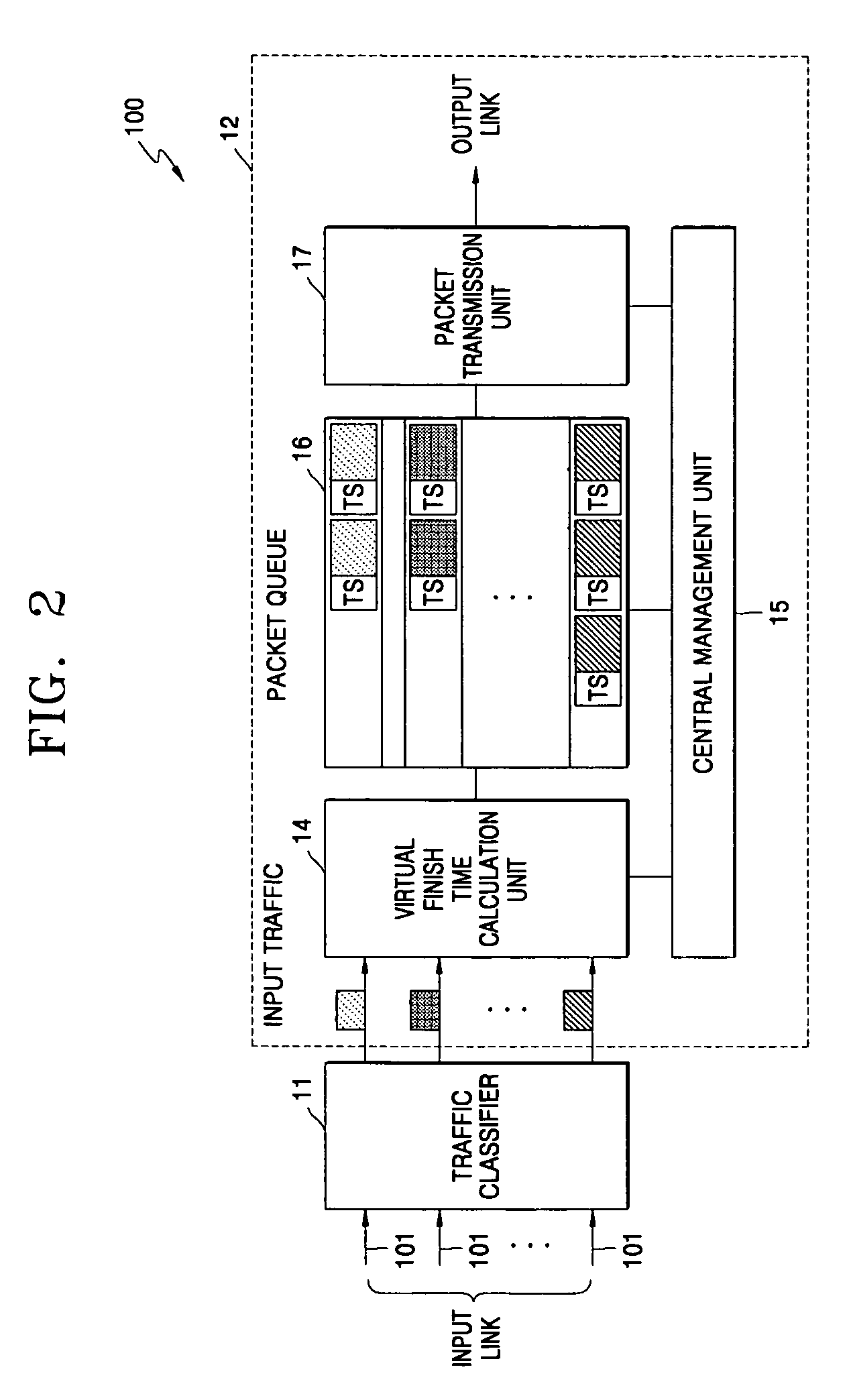
[0025]FIG. 1 shows a basic structure of a high-speed packet exchange node (for example, an ATM switch, a router system, etc.) which schedules packets entering from a plurality of input links at arbitrary speeds and sequentially multiplexes and transmits the scheduled packets in a high-speed packet exchange network to which the present invention is applied, such as an ATM or the Internet. The packet scheduling system according to the present invention is disposed at an input interface unit 10 and / or an output interface unit 30 of a high-speed packet exchange node.

[0026]Referring to FIG. 1, the high-speed packet exchange node comprises broadly an input interface unit 10, a switch fabric 20, and an output interface unit 30. The input interface unit 10 has m input interfaces (10a-10m) and the output interface unit 30 has n output interfaces (30a-30n).

[0027]Each input interface (10a-10m) installed in the input interface 10 performs the packet scheduling according to the present invention...


PUM


Abstract

Provided are a packet scheduling system and method capable of fair link resource distribution among a plurality of sessions requesting transmissions to an identical output link in input and output interfaces of a node in a high-speed packet exchange network such as an ATM network or the Internet. The packet scheduling system uses a traffic classifier which classifies traffic input from a plurality of input links, for each session; a central management unit which manages the agreed speed for each session and the virtual time of a system; a virtual finish time calculation unit which in response to the agreed speed and the system virtual time, calculates the virtual finish time of each packet for the traffic and attaches the calculated virtual finish time to the head of the packet as a time stamp. A packet queue which stores the packet sent by the virtual finish time calculation unit, for each session; and a packet transmission unit selects and outputs a packet having a shortest virtual finish time among packets stored in the packet queue.

Description

[0001]This application claims priority from Korean Patent Application No. 2002-79730, filed on Dec. 13, 2002, the disclosure of which is incorporated herein by reference in their entirety.BACKGROUND OF THE INVENTION[0002]1. Field of the Invention[0003]The present invention relates to a packet scheduling system and method, and more particularly, to a packet scheduling system and method capable of fair link resource distribution among a plurality of sessions requesting transmissions to an identical output link in input and output interfaces of a node, such as an asynchronous transfer mode (ATM) switch or a router, in a high-speed packet exchange network such as an ATM network or the Internet.[0004]2. Description of the Related Art[0005]Generally, packet scheduling algorithms are broken down into two methods according to operation modes of a server: one is a work-conserving method, by which the server provides services continuously unless there are no waiting packets in a queue, and th...

Claims


Application Information

Patent Timeline
Patent Type & Authority Patents(United States)
IPC IPC(8): H04J3/02H04L47/56H04L47/22
CPCH04L12/5693H04L47/50
Inventor KO, NAM SEOKKWAK, DONG YONG
Owner ELECTRONICS & TELECOMM RES INST
Why Eureka
Try Eureka