Camera adapter for optical devices, in particular microscopes

a technology of optical devices and adapters, which is applied in the field of camera adapters, can solve the problems of inability to record the image seen in the microscope, inability to connect the camera to the microscope, and inability to perform “double” examinations in a substantially longer tim

Inactive Publication Date: 2008-07-01
CARL ZEISS MEDITEC AG
View PDF17 Cites 15 Cited by
  • Summary
  • Abstract
  • Description
  • Claims
  • Application Information

AI Technical Summary

Problems solved by technology

While “normal” mirror reflex cameras can be used in these solutions, it is disadvantageous that binocular observation is not possible when the camera is connected.
Accordingly, it is not possible for the image seen in the microscope to be recorded at the same time by the video camera.
Further, this “double” examination takes substantially more time and is therefore more stressful for the patient.
However, the photographic attachment is not suitable for recording video sequences.
Further, it is disadvantageous that no observation is possible while photographic recordings are being made.

Method used


Image

  • Camera adapter for optical devices, in particular microscopes
  • Camera adapter for optical devices, in particular microscopes
  • Camera adapter for optical devices, in particular microscopes

Examples


Embodiment Construction

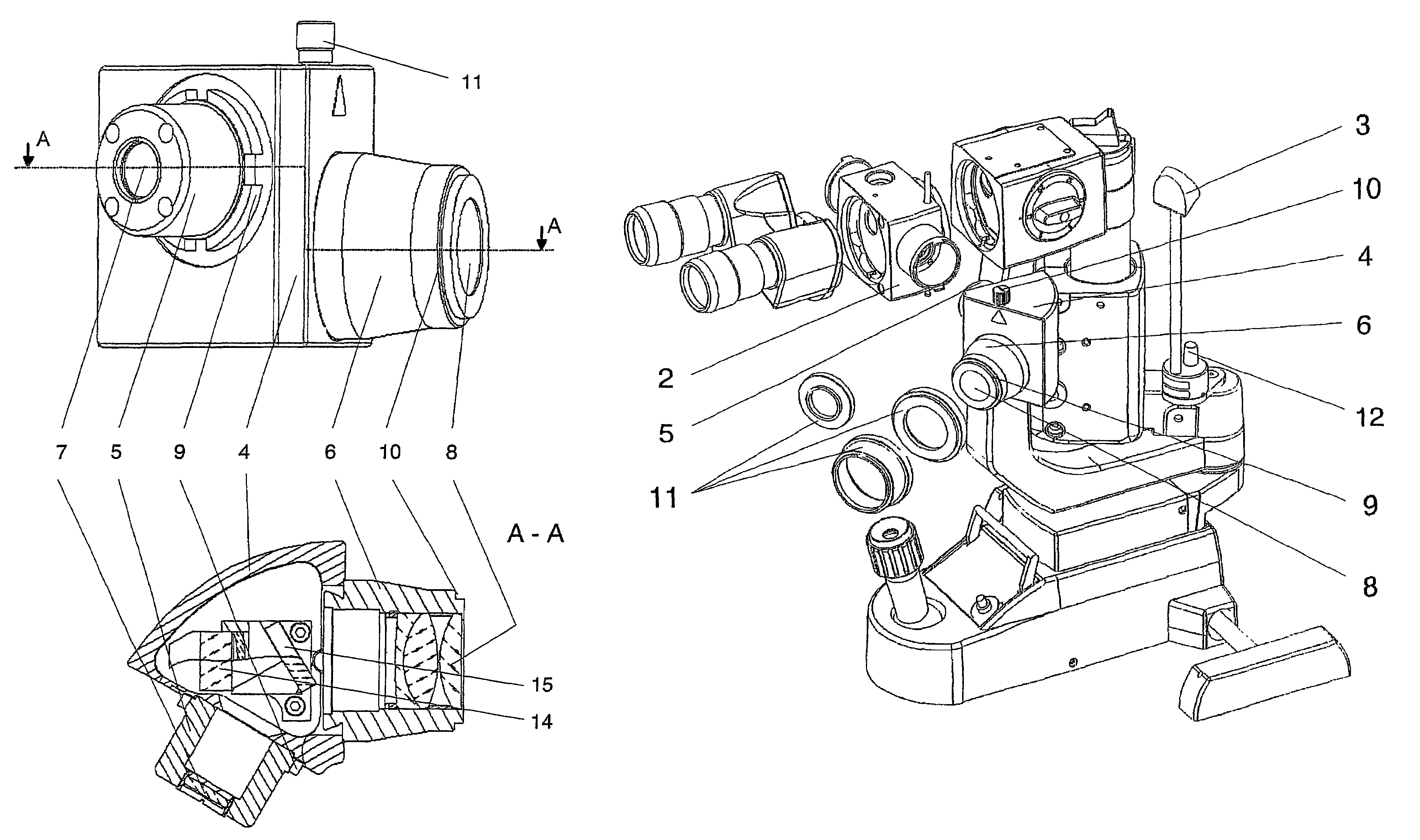
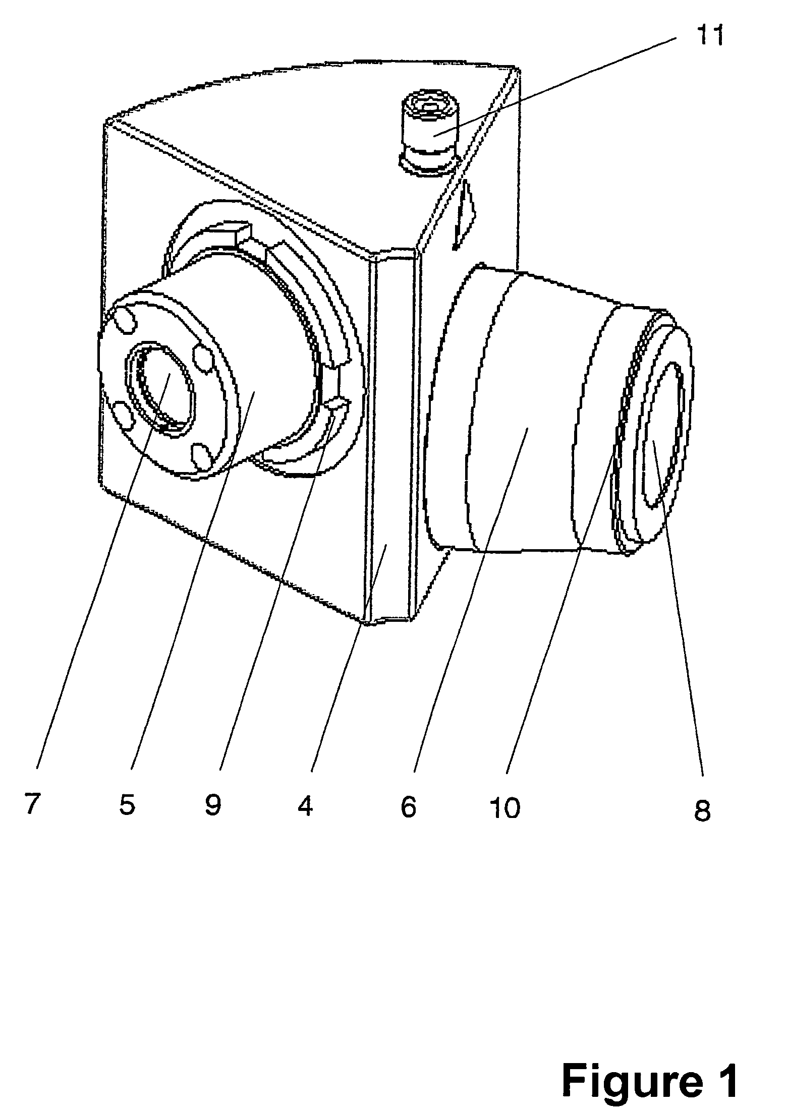
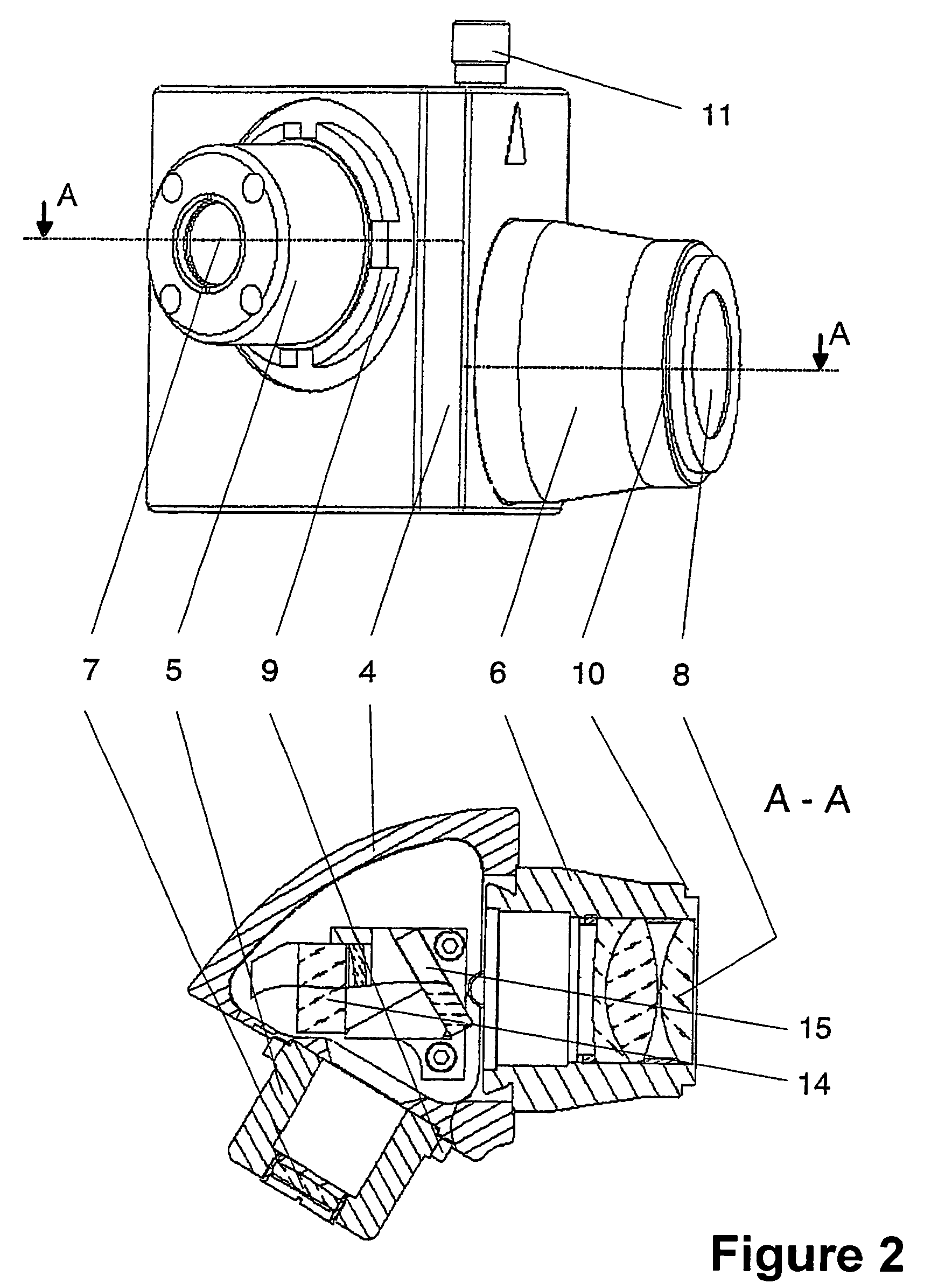
[0017]FIG. 1 shows the camera adapter for optical devices, particularly an ophthalmic microscope 1. An additional image out-coupling element 2, such as a swivel mirror or beam splitter, and a surrounding-field illuminator 3 for illuminating the object field when using slit projectors are required for photographic documentation of images in devices of the type mentioned above. The camera adapter to be arranged between the image out-coupling element 2 and the camera comprises a housing 4 with two connection pieces 5 and 6. The microscope-side connection piece 5 preferably has a quick-change device 9 such as is known from other microscope accessory units and has tube optics 7. The camera adapter is positively centered by this quick-change device 9 so that the optical axis of the camera coincides with that of the microscope 1 or of an optical channel of a stereo microscope.

[0018]In contrast, the camera-side connection piece 6 has a filter thread 10 and has eyepiece optics 8. The filter ...


PUM


Abstract

A camera adapter for optical devices, in particular microscopes. The present solution includes a camera adapter which enables any video cameras and photographic cameras to connect to an existing image out-coupling system, e.g., the beam splitter of a microscope. The adapter can also be used for stereo microscopes. The camera adapter is arranged between the image out-coupling element and the camera. Its housing has two connection pieces. The microscope-side connection piece has a quick-change device and the camera-side connection piece has a filter thread. The technical solution provides a camera adapter for connecting digital cameras to a microscope. By using intermediate rings, the camera adapter is suitable for different cameras and facilitates exchange of cameras. The camera can be positioned in such a way that the observer can view the object through the eyepiece as well as on the camera monitor without substantially changing his / her sitting position.

Description

CROSS-REFERENCE TO RELATED APPLICATIONS[0001]This application claims priority of International Application No. PCT / EP03 / 07876, filed Jul. 18, 2003, and German Application No. 102 40 720.7, filed Sep. 4, 2002, the complete disclosures of which are hereby incorporated by reference.BACKGROUND OF THE INVENTION[0002]a) Field of the Invention[0003]The present technical solution is directed to a camera adapter which makes it possible to connect any video cameras and photographic cameras to an existing image out-coupling system, e.g., the beam splitter of a microscope. The adapter can also be used for stereo microscopes and in particular for ophthalmic microscopes.[0004]b) Description of the Related Art[0005]According to the known prior art, lensless cameras are connected to a special optical output at the microscope or stereomicroscope by a corresponding coupling in order to document microscopic images. T2, C-mount or various bayonet connections, for example, are usually used as coupling s...

Claims


Application Information

Patent Timeline
Patent Type & Authority Patents(United States)
IPC IPC(8): G02B21/36G02B21/00H04N7/18H04N9/47G02B21/22G02B7/02G03B17/12G03B17/48G03B17/56
CPCG03B17/48G02B21/362
Inventor LUTHER, EGONKOSCHMIEDER, INGOBUCHHEISTER, JANHOFMANN, EBERHARDGERLACH, MARIORUEHLING, STEPHAN
Owner CARL ZEISS MEDITEC AG
Why Eureka
Try Eureka