Method and apparatus for performing error-detection and error-correction

a technology of error detection and error correction, applied in the direction of coding, instruments, code conversion, etc., can solve the problems of increasing the likelihood of communication errors, and the traditional methods of error detection and correction are not without drawbacks, so as to facilitate the detection and correction of errors

Active Publication Date: 2008-07-01
ORACLE INT CORP
View PDF3 Cites 14 Cited by
  • Summary
  • Abstract
  • Description
  • Claims
  • Application Information

AI Technical Summary

Benefits of technology

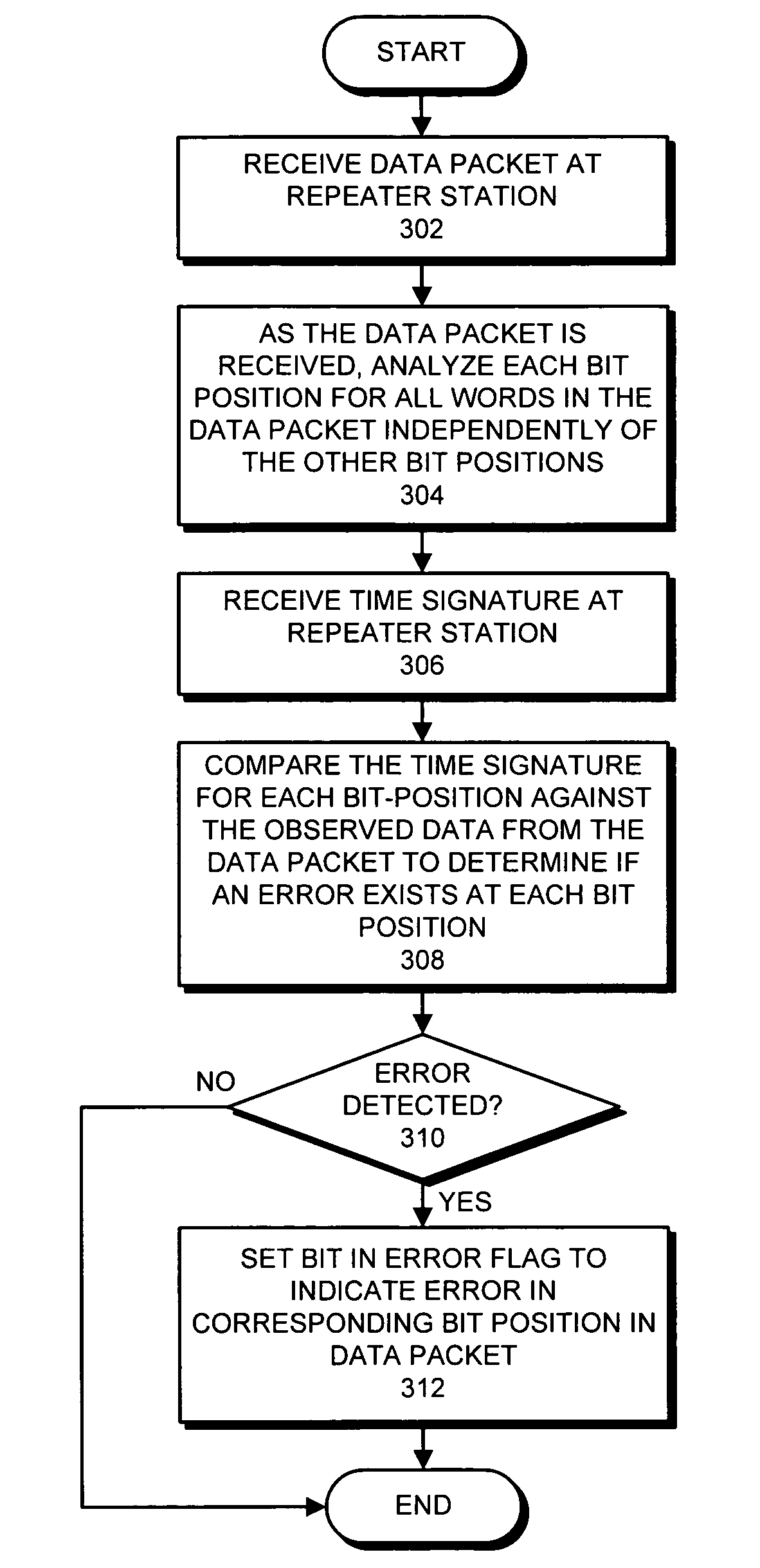
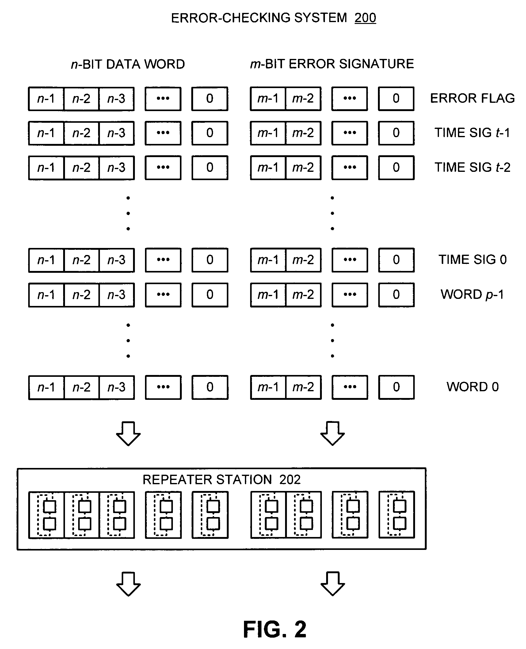
[0009]One embodiment of the present invention provides a system that facilitates detecting and correcting errors. The system operates by receiving a data packet comprised of p words on a communication pathway, wherein each bit of a word is received on a separate data line in a set of data lines that comprise the communication pathway. The system also receives a time signature t on the communication pathway, wherein t contains per-bit error information for the p words in the data packet. As the data packet is received, the system performs an error-detection operation on each data bit of the data packet in parallel, wherein the error-detection operation generates per-bit error information for each bit position across the p words in the data packet. Finally, the system compares the generated per-bit error-information with the corresponding per-bit error information in the time signature t to determine if there exists an error.

Problems solved by technology

These faster transmission rates increase the likelihood of communication errors.
These communication errors may cause a particular data bit to flip its value, or they may cause a bit to always transmit a zero or one regardless of its intended value.
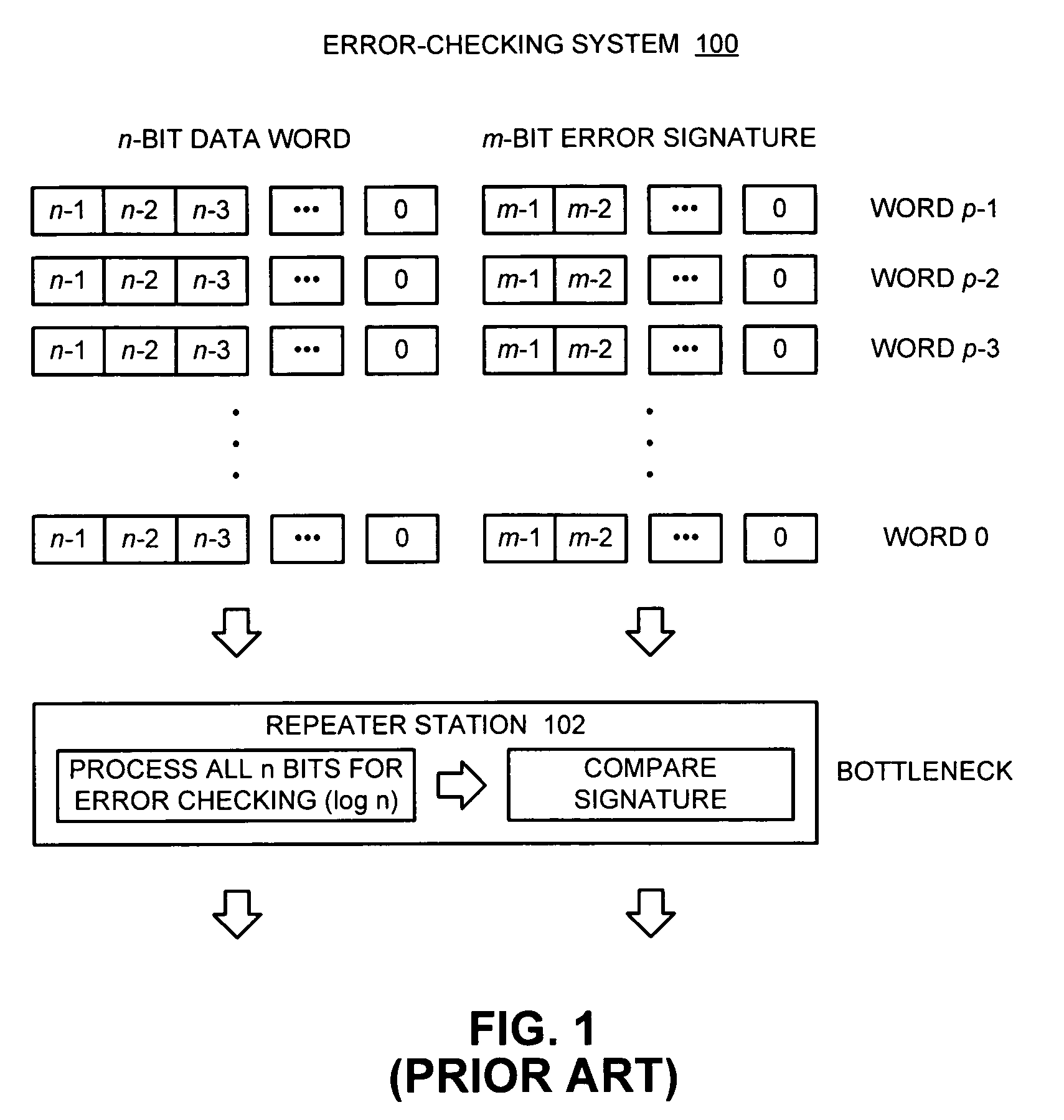
These traditional methods of error-detection and correcting are not without their drawbacks.
Because of the complexity and the time delay that results, several packets can pass through a station before it is determined that one of the words was corrupt.

Method used


Image

  • Method and apparatus for performing error-detection and error-correction
  • Method and apparatus for performing error-detection and error-correction
  • Method and apparatus for performing error-detection and error-correction

Examples


Embodiment Construction

[0019]The following description is presented to enable any person skilled in the art to make and use the invention, and is provided in the context of a particular application and its requirements. Various modifications to the disclosed embodiments will be readily apparent to those skilled in the art, and the general principles defined herein may be applied to other embodiments and applications without departing from the spirit and scope of the present invention. Thus, the present invention is not intended to be limited to the embodiments shown, but is to be accorded the widest scope consistent with the principles and features disclosed herein.

[0020]The data structures and code described in this detailed description are typically stored on a computer readable storage medium, which may be any device or medium that can store code and / or data for use by a computer system. This includes, but is not limited to, magnetic and optical storage devices such as disk drives, magnetic tape, CDs (...


PUM


Abstract

One embodiment of the present invention provides a system that facilitates detecting and correcting errors. The system operates by receiving a data packet comprised of p words on a communication pathway, wherein each bit of a word is received on a separate data line in a set of data lines that comprise the communication pathway. The system also receives a time signature t on the communication pathway, wherein t contains per-bit error information for the p words in the data packet. As the data packet is received, the system performs an error-detection operation on each data bit of the data packet in parallel, wherein the error-detection operation generates per-bit error information for each bit position across the p words in the data packet. Finally, the system compares the generated per-bit error-information with the corresponding per-bit error information in the time signature t to determine if there exists an error.

Description

BACKGROUND[0001]1. Field of the Invention[0002]The present invention relates to the design of communication pathways within digital systems. More specifically, the present invention relates to a method and an apparatus for performing error-detection and / or error-correction on data packets transmitted across multiple data lines within a digital system.[0003]2. Related Art[0004]As computer systems become increasingly faster, data must be transmitted between computer system components at increasingly faster rates. These faster transmission rates increase the likelihood of communication errors. These communication errors may cause a particular data bit to flip its value, or they may cause a bit to always transmit a zero or one regardless of its intended value. The goal of error-detection and error-correcting systems is to detect and recover from such communication errors.[0005]In a multi-hop communication network, error-detection / correction can be done at the receiver of the data and / or...

Claims


Application Information

Patent Timeline
Patent Type & Authority Patents(United States)
IPC IPC(8): H03M13/37
CPCH03M13/09H03M13/2906H03M13/098
Inventor TOURANCHEAU, BERNARDHO, RONALDDROST, ROBERT J.
Owner ORACLE INT CORP
Why Eureka
Try Eureka