
Laser level with temperature control device and temperature control method thereof

a technology of temperature control device and laser level, which is applied in the field of laser level, can solve the problems of no substantial aid in increasing affecting and limited number of temperature points measured in the factory for calibration, so as to achieve stable range, eliminate adverse effects on the measurement accuracy of the laser level due to temperature drift, and increase the effect of the measurement accuracy of the laser level

Inactive Publication Date: 2008-07-08
ASIA OPTICAL INT LTD
View PDF10 Cites 7 Cited by
  • Summary
  • Abstract
  • Description
  • Claims
  • Application Information

AI Technical Summary

Benefits of technology

[0006]Accordingly, one object of the present invention is to provide a laser level with temperature control device which cancels the adverse effects of temperature drift on the absolute accuracy of a tilt sensor of the laser level, increases the measurement accuracy of the laser level, and enlarges the acceptable ambient temperature range within which the laser level can normally work.
[0007]Another object of the present invention is to provide a temperature control method for a laser level, by which the working temperature of a tilt sensor of the laser level can be maintained in a stable range and can be calibrated to be close to the ambient temperature according to the ambient temperature variations, thereby canceling the adverse effects of temperature drift on the measurement accuracy of the laser level.
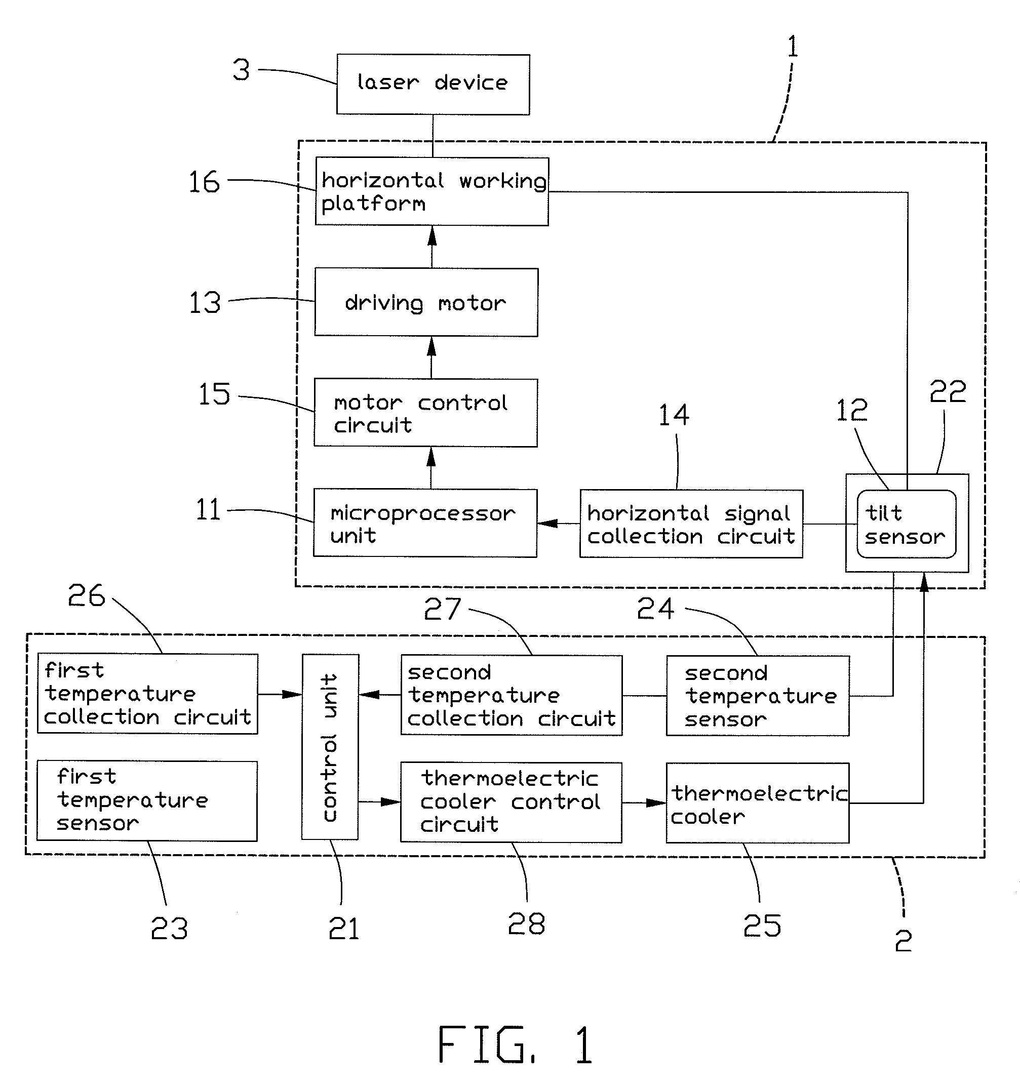
[0009]To achieve the second object of the present invention, a temperature control method for a laser level in accordance with the present invention comprises the following steps: first, obtaining the detected value of the tilt sensor at each calibration temperature point Tx that is set in P° C. increment (P is a constant) within the working temperature range T0 to T of the tilt sensor, Tx including T0, T1=T0+P, T2=T0+2P, . . . Tx=T0+XP; disposing the tilt sensor in a sealed thermal insulation chamber with internal temperature control; detecting the external temperature Tw outside the thermal insulation chamber by the first temperature sensor, if the external temperature Tw exceeds the working temperature range T0-T of the tilt sensor, that is, Tw<T0 or Tw>T, controlling the internal temperature inside the thermal insulation chamber to be equal to the lower working temperature limit T0 or the upper working temperature limit T; if the external temperature Tw is within the working temperature range T0-T of the tilt sensor, controlling the internal temperature inside the thermal insulation chamber to be Tx which satisfies the condition |Tx−Tw|<P / 2° C.; and proceeding with temperature drift compensation by means of software based on the predetected value of the tilt sensor at calibration temperature points Tx to increase the absolute accuracy of the laser level.
[0014]The laser level with temperature control device of the present invention is substantially different from those of the prior art in that the tilt sensor of the present laser level is disposed in a sealed thermal insulation chamber with internal temperature control. The temperature control device controls and adjusts the internal temperature inside the thermal insulation chamber so that the tilt sensor can work at a calibration temperature point close to the external temperature outside the thermal insulation chamber. Accordingly, the adverse effects on the measurement accuracy of the laser level due to temperature drift can be eliminated, and the working temperature of the tilt sensor can be maintained in a stable range. In addition, even if the external temperature outside the thermal insulation chamber is relatively greater or smaller than the upper or lower working temperature limit of the tilt sensor, the internal temperature inside the thermal insulation chamber can still be adjusted and maintained to be within the preset working temperature range of the tilt sensor, whereby level measurement of the tilt sensor can be performed normally. Therefore, by employing the present temperature control method for a laser level, the long existing temperature drift problem that adversely affects the absolute accuracy of a tilt sensor of the laser level can be effectively solved, the measurement accuracy of the laser level thus can be increased, and the acceptable ambient temperature range within which the laser level works can be expanded to allow the laser level to work at greater and lower ambient temperatures.

Problems solved by technology

However, it has been found that tilt sensors incorporated in most laser levels encounter with the problem of temperature drift with ambient temperature changes, which adversely affects measurement accuracy of the laser level.
For example, the measurement accuracy is 0.01° C., and the temperature drift coefficient is 0.01° / ° C. This solution helps the user roughly evaluate the measurement accuracy of the laser level according to the ambient temperature at measurement time, but provides no substantial aid in increasing the measurement accuracy of the laser level.
However, the number of temperature points measured in factory for calibration is limited.
Thus, it cannot be promised that a corresponding calibrated value can be found in the lookup table for every temperature variation in practical use.

Method used


Image

  • Laser level with temperature control device and temperature control method thereof
  • Laser level with temperature control device and temperature control method thereof
  • Laser level with temperature control device and temperature control method thereof

Examples


Embodiment Construction

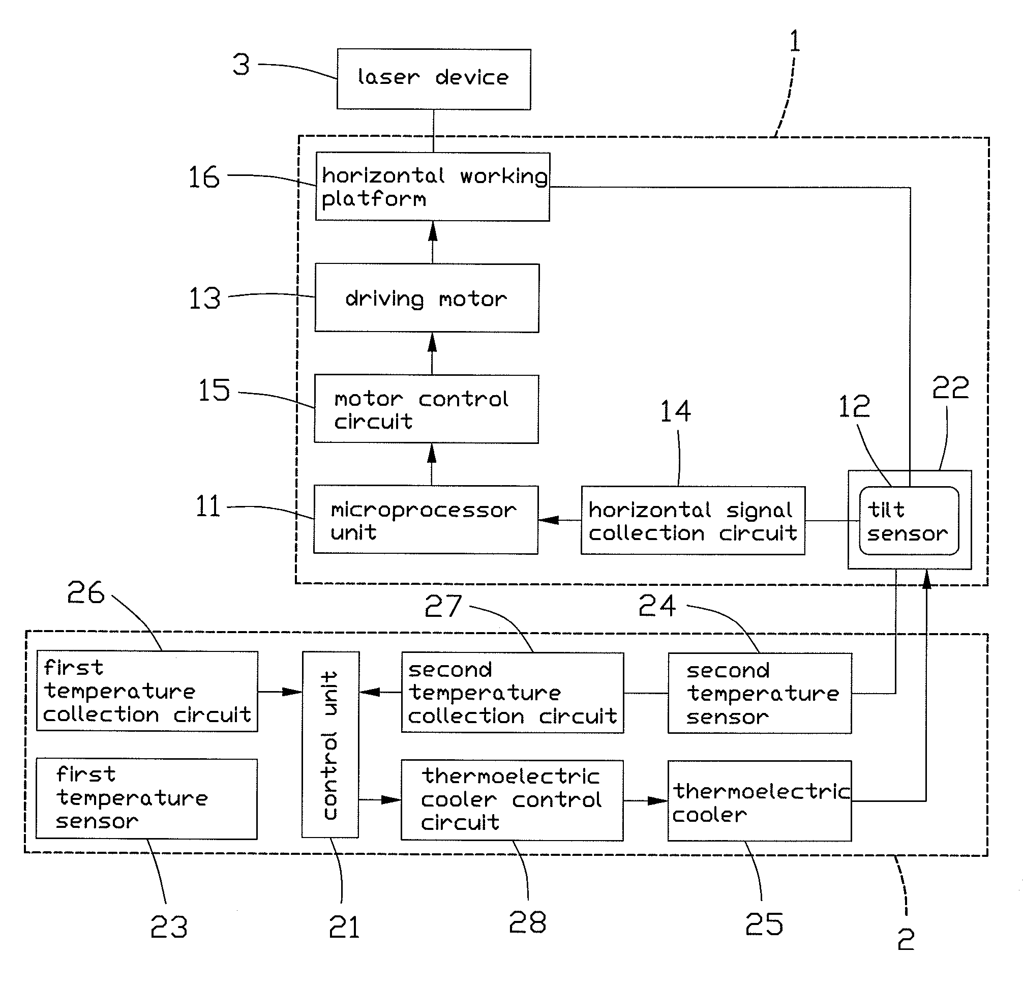
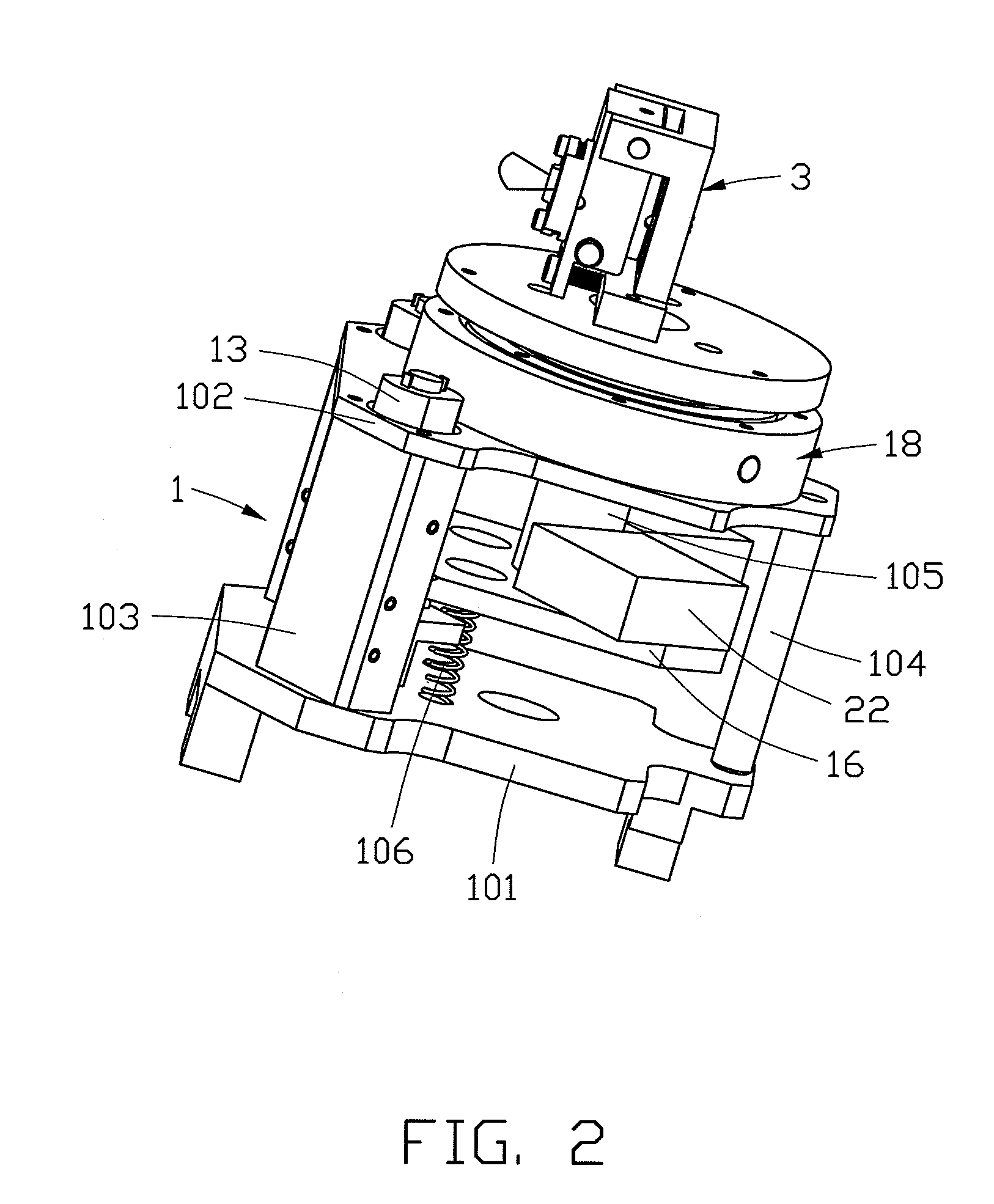
[0021]With reference to the drawings and in particular to FIGS. 1 and 2, which respectively show a block diagram and a perspective, assembled view of a laser level with temperature control device in accordance with the present invention, the laser level of the present invention comprises a level adjustment device 1, a temperature control device 2, and a laser device 3. The level adjustment device 1 comprises a microprocessor unit 11, a tilt sensor 12, an actuator in the form of a pair of driving motors 13, and a horizontal working platform 16. The tilt sensor 12 is disposed on the horizontal working platform 16. In operation, the tilt sensor 12 detects the horizontal inclination angle of the horizontal working platform 16 and outputs a signal to the microprocessor unit 11 through a horizontal signal collection circuit 14. The microprocessor unit 11 comprises a horizontal reference unit and a digital PID (Proportional-Integral-Derivative) control unit (not shown). The horizontal refe...


PUM


Abstract

A laser level with temperature control device (2) and the temperature control method thereof are disclosed. The temperature control device includes a thermal insulation chamber (22), a thermoelectric cooler (25), a control unit (21), and first and second temperature sensors (23, 24). The second temperature sensor is received in the thermal insulation chamber together with a tilt sensor (12). The control unit controls operation of the thermoelectric cooler according to the external and internal temperature signals respectively output by the first and second temperature sensors, so as to adjust the internal temperature inside the thermal insulation chamber to be a calibration temperature point close to the external temperature. Accordingly, the temperature drift problem can be addressed, and the working temperature of the tilt sensor can be maintained in a stable range. Further, the acceptable ambient temperature range within which the tilt sensor works can be expanded.

Description

BACKGROUND OF THE INVENTION[0001]1. Field of the Invention[0002]The present invention relates to a laser level, and in particular to a laser level with temperature control device for compensating adverse effects brought to the absolute measurement accuracy of a tilt sensor of the laser level by temperature drift, and a temperature control method thereof.[0003]2. Description of Prior Art[0004]A laser level utilizes the characteristic of excellent linearity of laser beams to measure or verify a horizontal line / surface or a vertical line / surface by a laser beam emitted by a laser emitter. Because of convenience in use and increasingly affordable cost, the laser levels are accepted by users and have been widely used in the constructing or assembling process of construction projects and large machines. U.S. Pat. Nos. 5,914,778, 6,762,830 and 7,013,571 each disclose a conventional laser level.[0005]However, it has been found that tilt sensors incorporated in most laser levels encounter wi...

Claims


Application Information

Patent Timeline
Patent Type & Authority Patents(United States)
IPC IPC(8): G01C5/00G01C9/00
CPCG01C15/004G01C9/00
Inventor CHIEN, PIE-YAULIU, HUA-TANGLI, YI-QIQI, YONG-CEJIAN, ZHANG-YONGCHEN, YUE-YE
Owner ASIA OPTICAL INT LTD
Learn More