Double action socket wrench

a socket wrench and double-action technology, applied in the field of socket wrenches, can solve the problems of limited success of these efforts, high number of custom parts that can have a detrimental impact on assembly and production, and wrenches of great complexity, so as to reduce friction and drag, and the effect of increasing the ratio of handle to sock

Inactive Publication Date: 2008-07-08
NELSON THOMAS P
View PDF8 Cites 9 Cited by
  • Summary
  • Abstract
  • Description
  • Claims
  • Application Information

AI Technical Summary

Benefits of technology

[0012]In another preferred embodiment, the hub assembly would include a bearing for the purpose of reducing friction and drag.
[0013]In another preferred embodiment, the invention also includes a bevel gear set with a ratio of greater than 1:1. This means the handle to socket ratio could be increased to gain a mechanical advantage.

Problems solved by technology

Some factors that have greatly limited the success of these efforts are ratchet mechanism location, the type of ratchet mechanism used and handle mounting and retention.
This resulted in wrenches of great complexity and a high number of custom parts that can have a detrimental impact on assembly and production.
(U.S. Pat. No. 4,406,184) taught ratchet mechanism location, its efforts to provide sufficient means to retain the handle had questionable results at best.
This situation may cause the handle to suddenly come unlocked, the handle retaining screw to impact the side of its slot, subjecting it to considerable side loads, and more likely than not causing eventual failure of the handle retaining screw.
Again, handle retention becomes a significant problem.
Another problem with the ratcheting screwdriver solution is the selection of ratchet mechanisms.
Another problem to consider is deflection and / or bending.
When side loading the handle, if the load is conveyed directly to the drive shaft or some type of coupling device, there is a great possibility that the shaft or coupler will become jammed, distorted or bent, leaving the tool inoperable.
Again, a handle that is able to move along the axis of the wrench, it seems, could easily become disengaged from the desired setting, having a severe impact on tool function.

Method used


Image

  • Double action socket wrench
  • Double action socket wrench
  • Double action socket wrench

Examples


Embodiment Construction

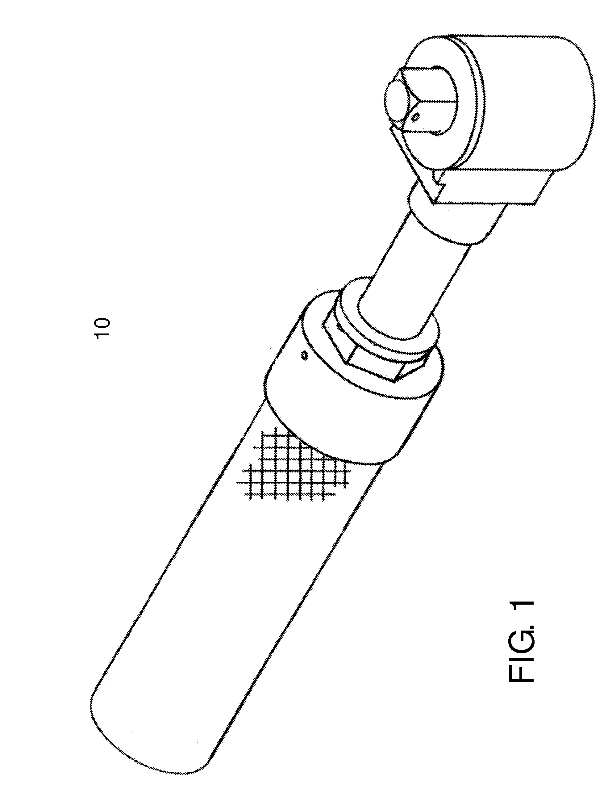
[0029]Drawings and descriptions combine to refer to socket wrench 10 (FIG. 1) that is the invention. Anterior refers to end nearest the right-hand margin as drawn. Posterior refers to the distal end.

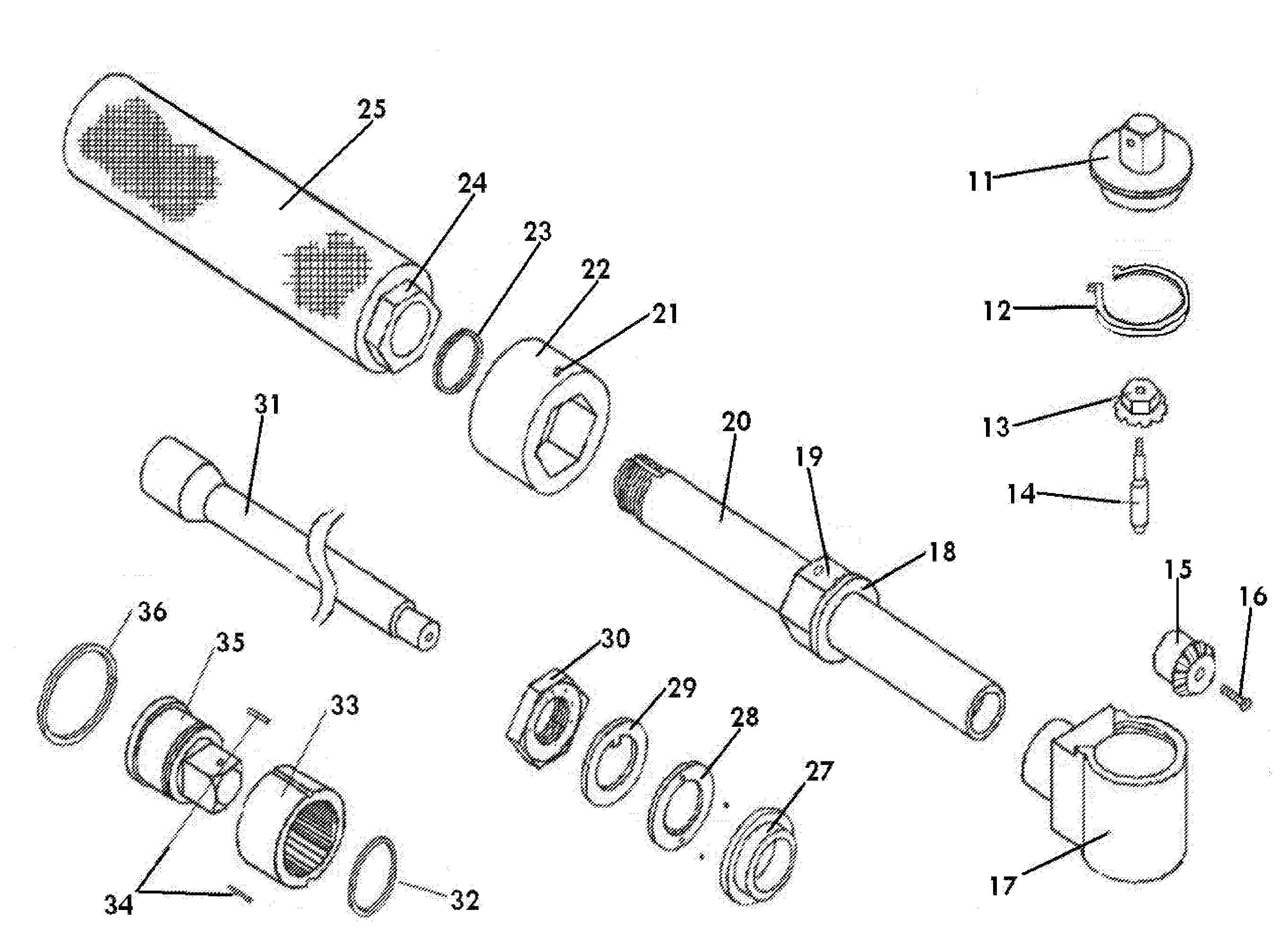
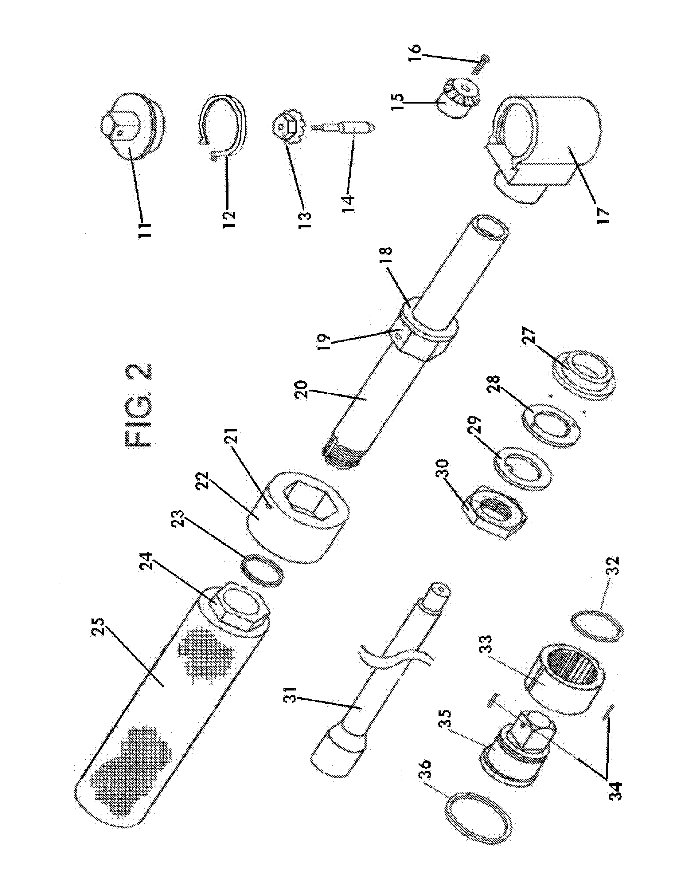
[0030]Three of the main parts of socket wrench 10 are body 20 (FIGS. 2 and 4), head 17 and handle 25. Head 17 is either permanently mounted in a fixed position to the anterior end of body 20 (FIGS. 1,2,3 and 4) or is an integral part of body 20 (FIGS. 5 and 6). Handle 25 is rotatably mounted to the posterior end of body 20.

[0031]Body 20, is an elongated tube, having a hollow, circular interior section running through its length, open at both ends. Posterior end of body 20 has as some of its exterior portions, a threaded segment corresponding to lock nut 30 and a grooved keyway corresponding to inside tab washer 29. The anterior end has as some of its portions, an enlarged circular opening that forms a cavity corresponding to the hub of second miter gear 15. Body 20 also has as one of its...


PUM


Abstract

This invention relates to bi-directional ratcheting socket wrenches having two modes of operation that can be used independently or simultaneously and having only one ratchet mechanism. This invention can rotate a work piece by being rotated around the socket axis as is common to socket wrenches, the handle can be rotated around its axis or the two motions can be combined as one fluid motion. This can be accomplished in either direction of rotation while permitting the ability to reposition the wrench and/or the handle. Again, this is achieved using a single ratchet mechanism. This invention also provides a means to lock the handle in position relative to the wrench itself, a means to sufficiently retain the handle without impeding handle rotation, a means to mount the handle on a bearing and a means to provide alternative embodiments of the wrench to further increase its usefulness in confined areas.

Description

FIELD OF INVENTION[0001]The present invention relates to a socket wrench and its preferred embodiments having two modes of operation that can be employed independently or simultaneously, having a lockable handle and having a single ratchet mechanism.BACKGROUND OF THE INVENTION[0002]Considerable effort has been spent trying to perfect a socket wrench having two modes of operation that can be used independently or simultaneously. Some factors that have greatly limited the success of these efforts are ratchet mechanism location, the type of ratchet mechanism used and handle mounting and retention.[0003]The prior art of Singleton (U.S. Pat. No. 4,907,476) is an example of ratchet mechanism location effecting handle and ratchet mechanism operation. In that prior art, the ratchet mechanism is in the head, allowing the wrench to be rotated and repositioned as is a common socket wrench, but the t-handle can only be rotated in one direction and not repositioned. This is due to the fact that ...

Claims


Application Information

Patent Timeline
Patent Type & Authority Patents(United States)
IPC IPC(8): B25B17/00B25B13/46
CPCB25B13/46B25B17/00B25B13/481B25B13/465
Inventor NELSON, THOMAS PAUL
Owner NELSON THOMAS P
Why Eureka
Try Eureka