
Color OLED display system having improved performance

a display system and color technology, applied in the field of organic light-emitting diodes (oled) and full-color display devices, can solve the problems of reducing the visibility or perceived quality of the display, inefficient display limits the time of the device, and not particularly power-efficient known red and blue emissive materials, so as to improve power efficiency and display life, and reduce the luminance of the display

Active Publication Date: 2008-07-08
GLOBAL OLED TECH
View PDF30 Cites 126 Cited by
  • Summary
  • Abstract
  • Description
  • Claims
  • Application Information

AI Technical Summary

Benefits of technology

[0013]The advantages of this invention include an OLED display system that allows improved pow

Problems solved by technology

However, the known red and blue emissive materials are not particularly power efficient.
While power efficiency is always desirable, it is particularly desirable in portable applications because an inefficient display limits the time the device can be used before the power source is recharged.
For this reason, under certain circumstances the end user may wish to reduce the power consumption of a display by making tradeoffs in display performance, which may have the effect of reducing the visibility or perceived quality of the display under various conditions.
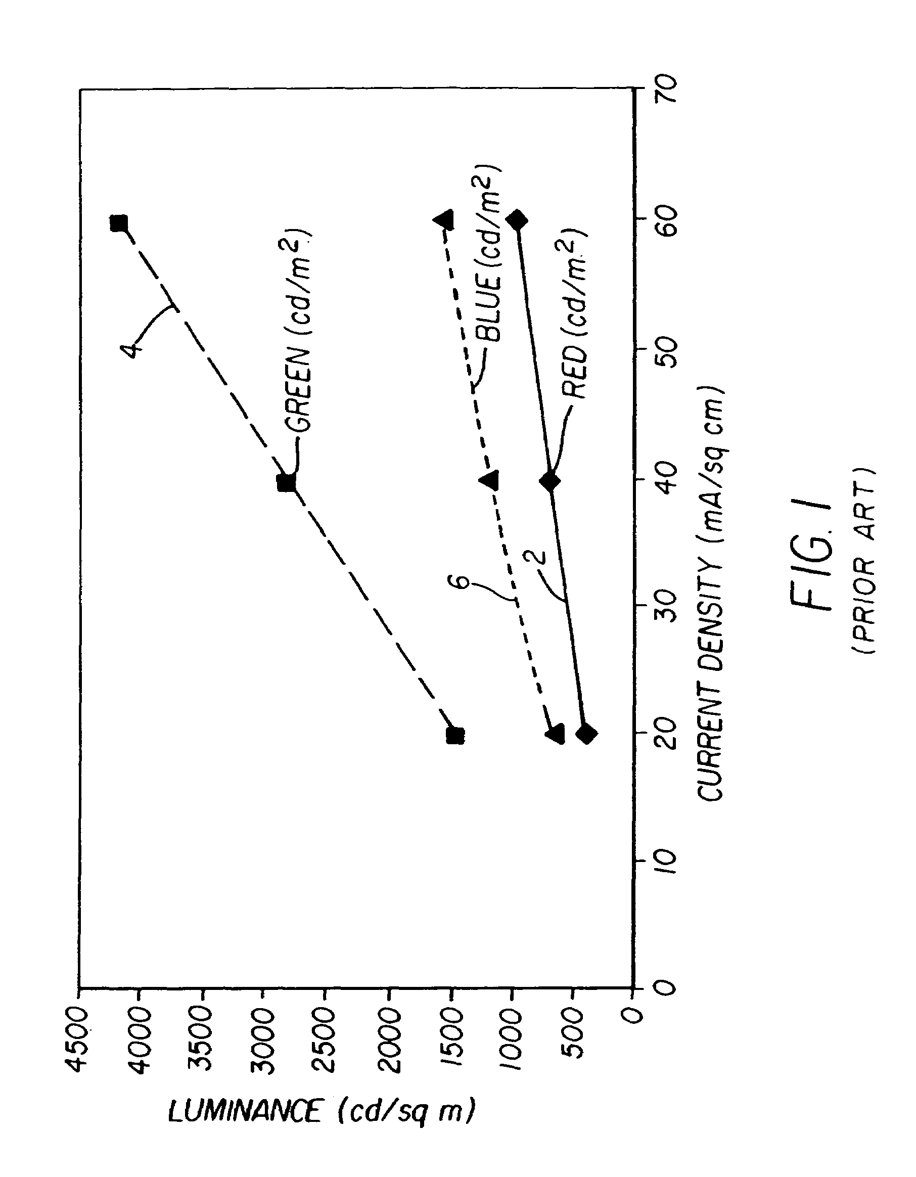
However, any previous method that has been used to adjust the luminance of the display has required proportionally more power with increases in display luminance.
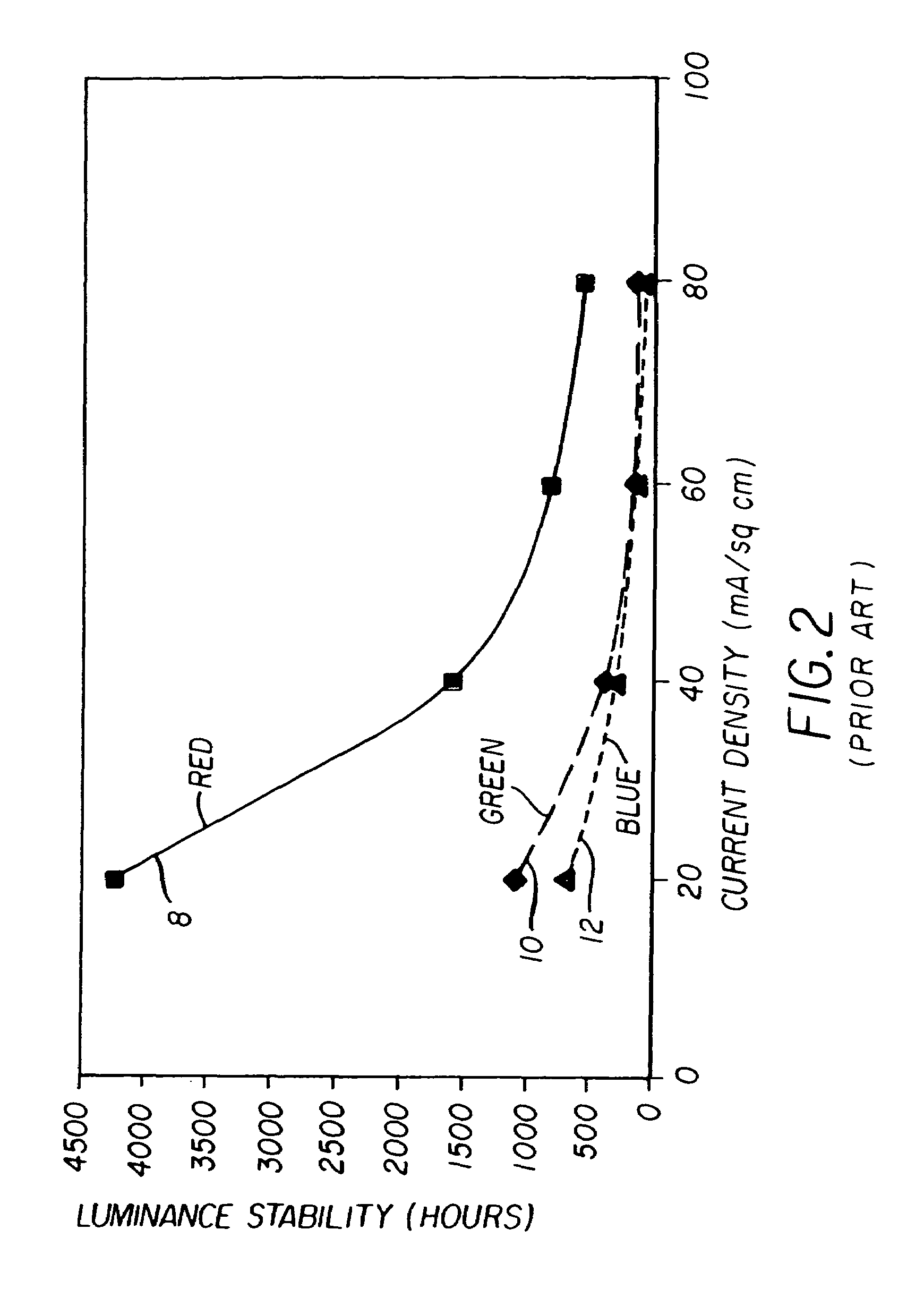
Unfortunately, increasing the current density used to drive an OLED not only increases the power required to drive the OLED but also reduces the lifetime of the OLED. FIG. 2 shows typical functions that describe the time required for an OLED to lose half of its luminance as a function of the current density used to drive the OLED.
Therefore, increasing the luminance of an OLED display not only increases the power needed to drive the OLED display device but can significantly reduce the lifetime of the OLED display device.

Method used


Image

  • Color OLED display system having improved performance
  • Color OLED display system having improved performance
  • Color OLED display system having improved performance

Examples


Embodiment Construction

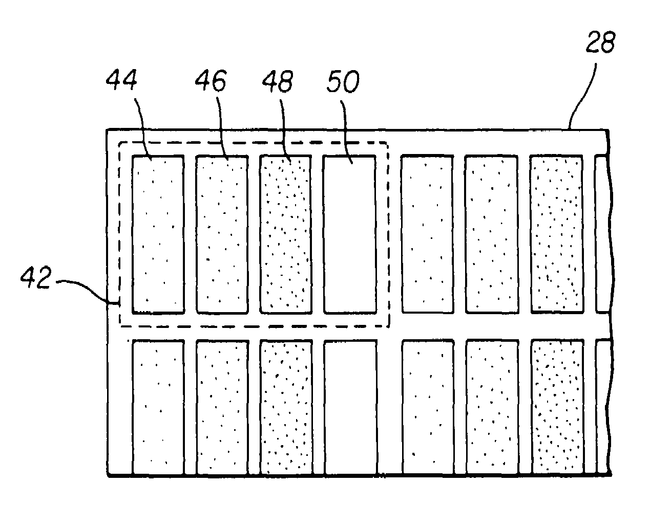
[0023]The present invention is directed to a color OLED display system comprising a color OLED display, a control signal, and a controller for driving the color OLED display device in response to the control signal. More particularly, the present invention is directed to display systems that include a full-color display device having three or more emissive OLEDs, providing three or more primary colors that define the color gamut of the display device. The display system comprises an OLED display including an array of light emitting pixels, each pixel having a plurality of OLEDs for emitting different colors of light specifying a color gamut; a control signal; and a display driver for receiving a color display signal representing a relative luminance and color to be produced for each pixel of the display and generating a converted color display signal for driving the OLEDs in the display, the display driver being responsive to the control signal for controlling the color-gamut satura...


PUM


Abstract

An OLED display system includes a) an OLED display including an array of light emitting pixels, each pixel having a plurality of OLEDs for emitting different colors of light specifying a gamut wherein one of the OLEDs has a power efficiency or lifetime different from the power efficiency or lifetime of at least one of the other OLEDs; b) a control signal; and c) a display driver for receiving a color display signal representing a relative luminance and color to be produced for each pixel of the display and generating a converted color display signal for driving the OLEDs in the display, wherein the display driver is responsive to the control signal for controlling the color gamut saturation of light produced by the OLEDs to reduce power consumption or increase lifetime of at least one of the OLEDs.

Description

CROSS-REFERENCE TO RELATED APPLICATIONS[0001]This is a continuation-in-part of U.S. Ser. No. 10 / 320,195, filed Dec. 16, 2002 now U.S. Pat. No. 7,230,594, and a continuation-in-part of U.S. Ser. No. 10 / 387,953, filed Mar. 13, 2003 now U.S. Pat. No. 7,184,067, the disclosures of which are incorporated by reference herein in their entireties.FIELD OF THE INVENTION[0002]The present invention relates to organic light emitting diode (OLED), full-color display devices and, more particularly, to OLED color displays with improved power efficiency or extended display lifetime.BACKGROUND OF THE INVENTION[0003]Color, digital image display devices are well known and are based upon a variety of technologies such as cathode ray tubes, liquid crystal and solid-state light emitters such as Organic Light Emitting Diodes (OLEDs). In a common OLED color display device a pixel includes red, green, and blue colored OLEDs. By combining the illumination from each of these three OLEDs in an additive color s...

Claims


Application Information

Patent Timeline
IPC IPC(8): G09G5/02G09G3/20G09G3/32H01L27/32
CPCG09G3/3225H01L27/3211H01L27/3213G09G3/3216G09G3/2011H01L27/322G09G2300/0452G09G2320/0233G09G2320/029G09G2320/041G09G2320/043G09G2320/0606G09G2320/0626G09G2320/066G09G2330/021G09G2360/144H10K59/351H10K59/38
Inventor MILLER, MICHAEL E.COK, RONALD S.ARNOLD, ANDREW D.MURDOCH, MICHAEL J.
Owner GLOBAL OLED TECH
Learn More