Image reading apparatus using image reading lens

a reading apparatus and reading technology, applied in the direction of mountings, optics, instruments, etc., can solve the problems of affecting the image reading, requiring a higher assembling precision, and complicated structure inside the carriage b>97/b>, so as to reduce the magnification error in the sub-scan direction.

Inactive Publication Date: 2008-07-08
CANON KK
View PDF9 Cites 8 Cited by
  • Summary
  • Abstract
  • Description
  • Claims
  • Application Information

AI Technical Summary

Benefits of technology

[0025]The present invention provides an image reading apparatus using an image reading lens by which both the field curvature aberration and the magnification error in the sub-scan direction can be well reduced.
[0037]Briefly, in accordance with the present invention, an image reading apparatus using an image reading lens by which both the field curvature aberration and the magnification error in the sub-scan direction can be well reduced, is accomplished.

Problems solved by technology

With these methods, however, the structure inside the carriage 97 becomes complicated, and this requires a higher assembling precision.
Moreover, there is an additional problem that the imaging performance deteriorates in proportion to the profile irregularity of the reflecting mirror and the reflection times, which adversely influences the image reading.
However, when only one anamorphic surface is used in an attempt to reducing both the field curvature aberration and a magnification error in the sub-scan direction, there is only one degree of freedom.
Therefore, it is very difficult to control these two factors independently of each other.

Method used


Image

  • Image reading apparatus using image reading lens
  • Image reading apparatus using image reading lens
  • Image reading apparatus using image reading lens

Examples


numerical example 1

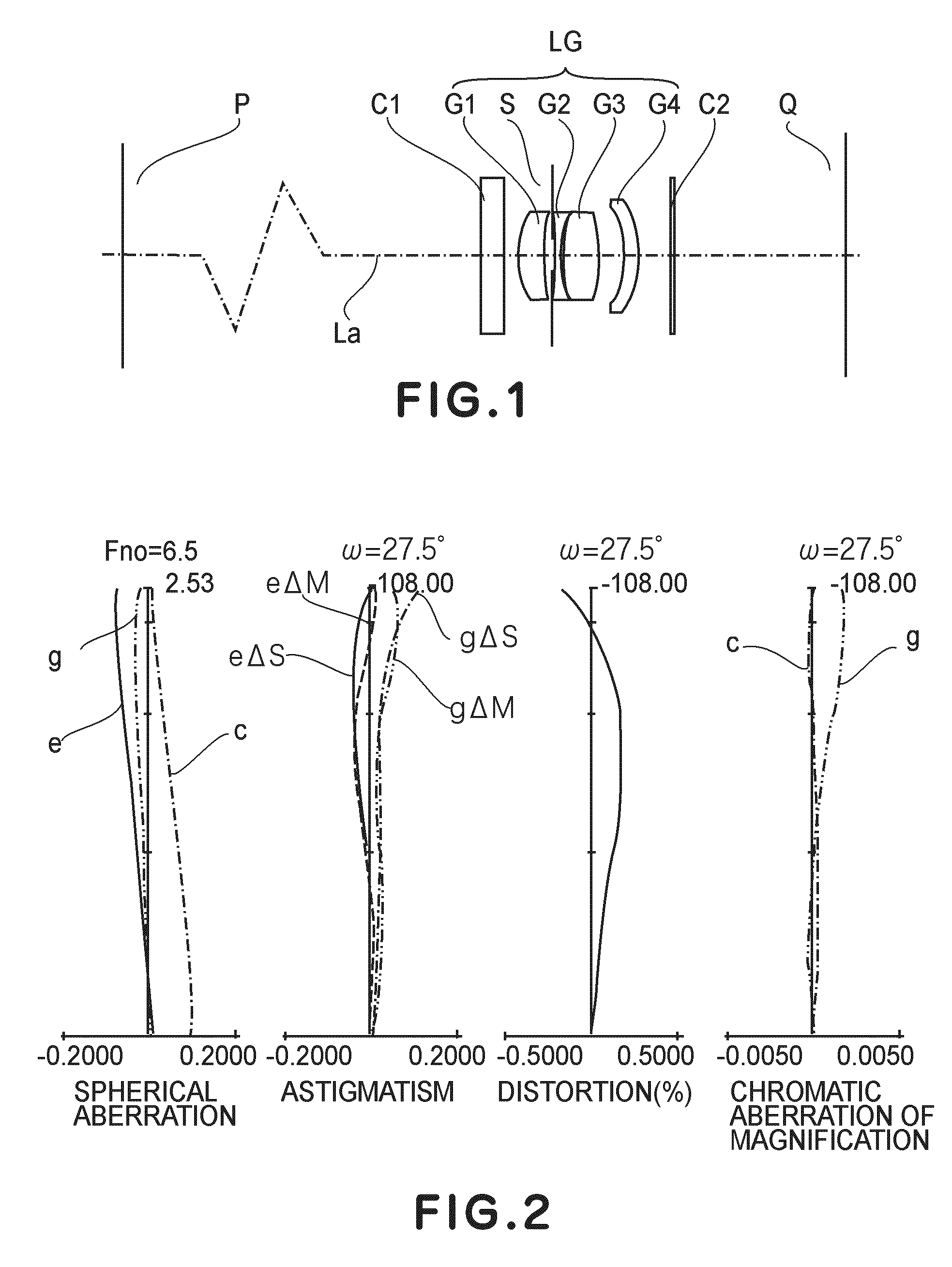
[0113]The image reading lens LG of Numerical Example 1 has an F number 6.5 which is necessary and sufficient for use in an image scanner. As shown in FIG. 2, aberrations from the axial point to the abaxial point are reduced enough, and high imaging performance is obtained.

[0114]As for the line sensor (CCD) to be used in combination, anyone may be used provided that the magnification is 0.189×. The numerical values of conditional expressions (1)-(5) are shown in Table 7 below. All these values satisfy corresponding conditional expressions (1)-(5).

[0115]Here, even if a CCD for 2400 dpi having different color sensors of R-G and G-B with a sensor array spacing of 96 μm and a pixel size of 2 μm, is used, it has been confirmed by the ray tracing simulation that the color drift due to the error of the sub-scan magnification is around 0.6 pixel. It is sufficiently good performance.

numerical example 2

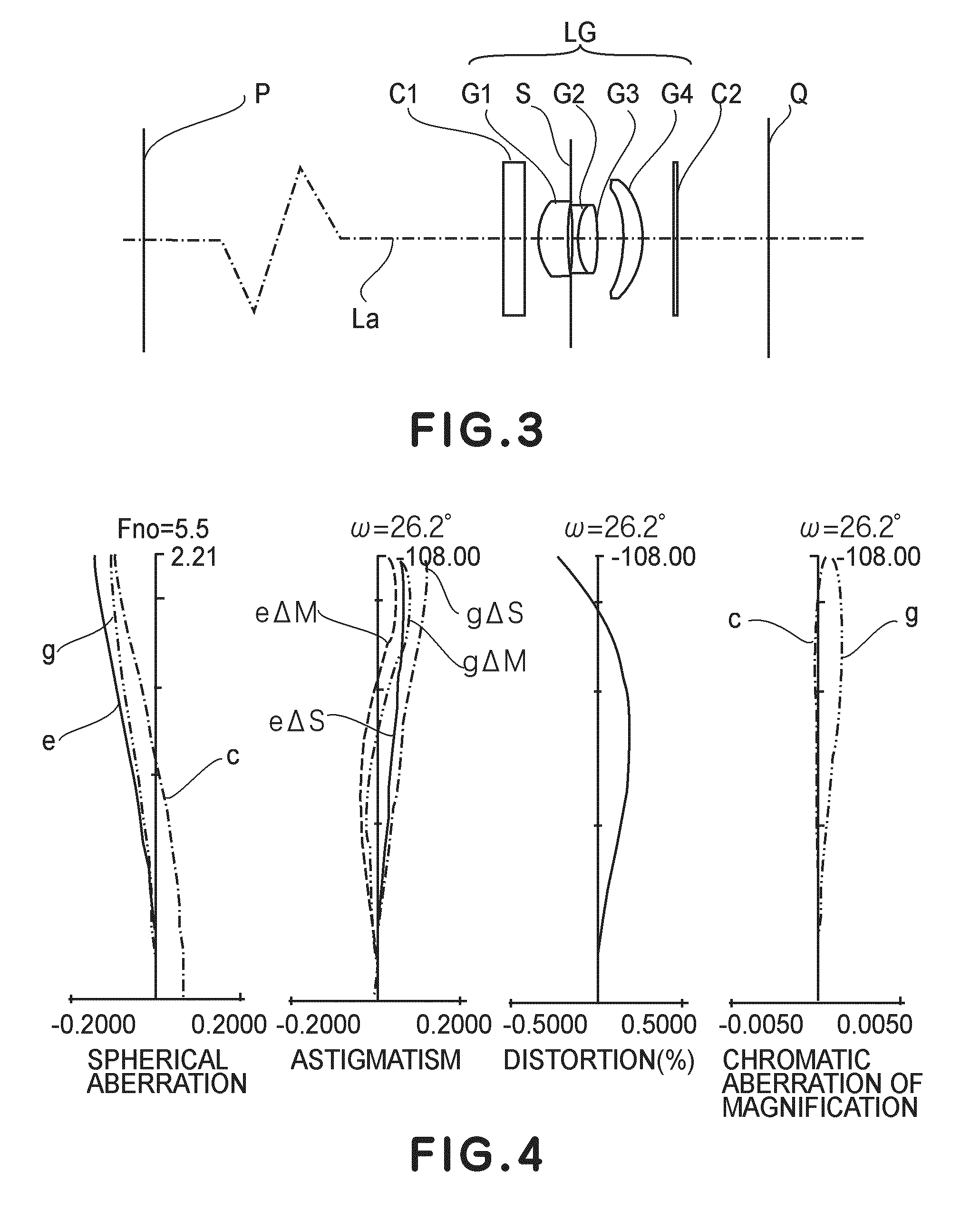
[0116]The image reading lens LG of Numerical Example 2 has an F number 5.5 which is necessary and sufficient for use in a digital copying machine. As shown in FIG. 4, aberrations from the axial point to the abaxial point are reduced enough, and high imaging performance is obtained.

[0117]As for the line sensor (CCD) to be used in combination, anyone may be used provided that the magnification is 0.124×. The numerical values of conditional expressions (1)-(5) are shown in Table 7 below. All these values satisfy corresponding conditional expressions (1)-(5).

[0118]Here, even if a CCD for 600 dpi having different color sensors of R-G and G-B with a sensor array spacing of 63 μm and a pixel size of 5.25 μm, is used, it has been confirmed by the ray tracing simulation that the color drift due to the error of the sub-scan magnification is around 0.3 pixel. It is sufficiently good performance.

numerical example 3

[0119]The image reading lens LG of Numerical Example 3 has an F number 5.0 which is necessary and sufficient for use in a digital copying machine. As shown in FIG. 6, aberrations from the axial point to the abaxial point are reduced enough, and high imaging performance is obtained.

[0120]As for the line sensor (CCD) to be used in combination, anyone may be used provided that the magnification is 0.124×. The numerical values of conditional expressions (1)-(5) are shown in Table 7 below. All these values satisfy corresponding conditional expressions (1)-(5).

[0121]Here, even if a CCD for 1200 dpi having different color sensors of R-G and G-B with a sensor array spacing of 63 μm and a pixel size of 2.625 μm, is used, it has been confirmed by the ray tracing simulation that the color drift due to the error of the sub-scan magnification is around 0.4 pixel. It is sufficiently good performance.

[0122]Now, Table 7 shows the relationship between the abovementioned conditional expressions (1)-(...


PUM


Abstract

An image reading apparatus with an image reading lens configured to reduce a field curvature and a magnification error in the sub-scan direction, includes a photoelectric conversion element having picture elements arrayed in the main-scan direction, and an image reading lens for imaging imagewise information on a surface of an original, upon a light receiving surface of the photoelectric conversion element, the image reading lens including at least one anamorphic lens having anamorphic surfaces formed at a light entrance surface and a light exist surface thereof, respectively, wherein, when a sectional shape of the anamorphic surface in a main-scan section which contains an optical axis of the image reading lens and the main-scan direction, is taken as a meridional, a curvature of a sagittal of the anamorphic surface defined within a plane being perpendicular to the main-scan section and containing a normal to the anamorphic surface at an arbitrary position in the meridional direction, changes continuously along the meridional direction from the optical axis.

Description

FIELD OF THE INVENTION AND RELATED ART[0001]This invention relates to an image reading apparatus using an image reading lens. More particularly, the invention is suitable usable for an image reading apparatus such as an image scanner, a copying machine or a facsimile machine, for example, in which the optical performance of the image reading lens having an anamorphic lens is best utilized to perform high-precision image reading.[0002]Various proposals have been made in regard to image reading apparatuses such as image scanner or digital copying machine, for example.[0003]FIG. 10 is schematic diagram of a main portion of the structure of a conventional image reading apparatus.[0004]In FIG. 10, denote at 92 is an original table (original table glass) on which an original 91 is placed. Denoted at 93 is an illumination system which comprises a xenon tube, halogen lamp or light emitting diode array, for example. Denoted at 94a-94e are reflecting mirrors which function to bend the light b...

Claims


Application Information

Patent Timeline
Patent Type & Authority Patents(United States)
IPC IPC(8): G02B7/00G02B13/08H04N1/04G02B26/08
CPCG02B13/0005G02B26/125G02B13/08
Inventor HAYASHIDE, TADAOSUGIYAMA, TAKAYUKI
Owner CANON KK
Why Eureka
Try Eureka