Combustion control method for a direct-injection controlled auto-ignition combustion engine

a combustion engine and control method technology, applied in the direction of electric control, machines/engines, mechanical equipment, etc., to achieve the effect of relaxing geometric constraints on the design of the combustion chamber and improving individual cylinder combustion control

Active Publication Date: 2008-07-15
GM GLOBAL TECH OPERATIONS LLC
View PDF15 Cites 1 Cited by
  • Summary
  • Abstract
  • Description
  • Claims
  • Application Information

AI Technical Summary

Benefits of technology

[0006]The present invention comprises a powertrain, and a control method therefor, wherein ignition of a combustible charge in a combustion chamber of either of a homogeneous- or stratified-charge, controlled auto-ignition internal combustion engine equipped with in-cylinder fuel-injection and a spark ignition device is controlled. The method comprises generating a spark-discharge plasma channel between the electrodes of the spark ignition device, to generate a chemical reaction in the combustion chamber. The spark-discharge plasma channel is drawn toward the combustible charge thus advancing the phasing of controlled auto-ignition combustion.
[0007]Potential benefits of the present invention include: 1) improved individual cylinder combustion control during speed and load transients in a multi-cylinder engine and 2) relaxed geometric constraints on combustion chamber design. The present invention applies to controlled auto-ignition combustion engines operated with any single- or multi-component fuel.

Problems solved by technology

There are many geometrically constrained design limitations for optimal engine operation which affect the ability of the spark-discharge plasma channel to be located at an ignitable region of the fuel-air mixture; these included relative position between the spark plug, the fuel injector, combustion-chamber geometry, and piston-bowl geometry.

Method used


Image

  • Combustion control method for a direct-injection controlled auto-ignition combustion engine
  • Combustion control method for a direct-injection controlled auto-ignition combustion engine
  • Combustion control method for a direct-injection controlled auto-ignition combustion engine

Examples


Embodiment Construction

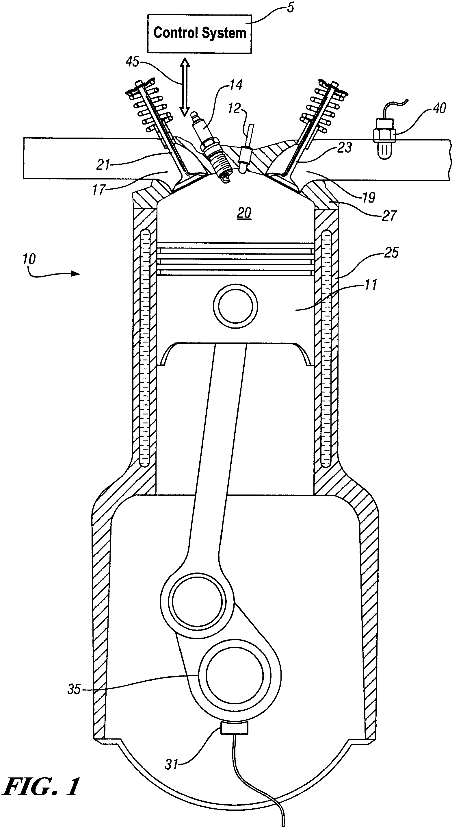
[0012]Referring now to the drawings, wherein the depictions are for the purpose of illustrating the invention only and not for the purpose of limiting the same, FIG. 1 depicts a powertrain, comprising an internal combustion engine 10 and control system 5 which has been constructed in accordance with an embodiment of the present invention. The engine 10 preferably comprises a gasoline direct-fuel injection, spark-ignited, four-stroke internal combustion engine operable in a controlled auto-ignition process, i.e., a homogeneous-charge, compression-ignition (‘HCCI’) engine. It is understood that the invention described herein is applicable to other engine configurations, e.g., engines configured to operate in a stratified-charge mode.

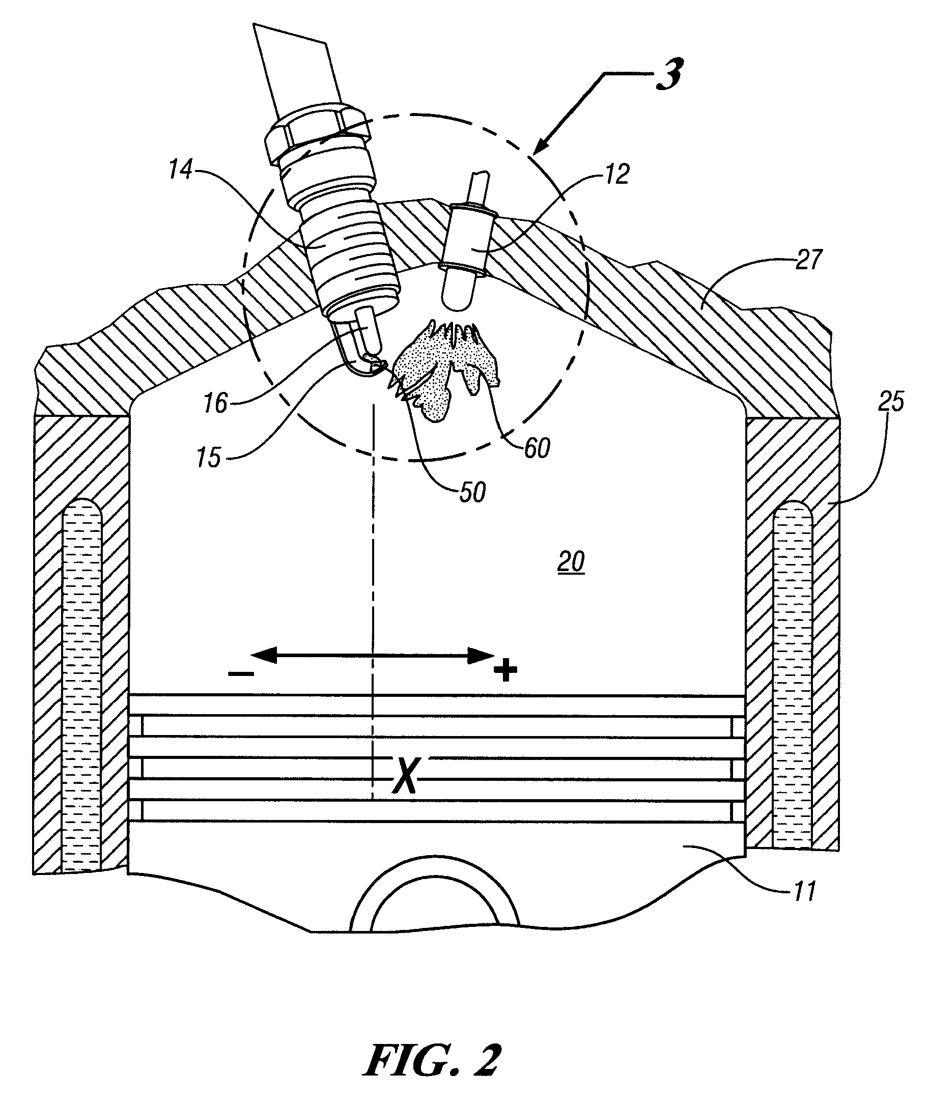
[0013]The exemplary engine comprises a plurality of variable volume combustion chambers 20, each defined by a closed-end cylinder formed in an engine block 25. A moveable piston 11 defines, with walls of the cylinder, the variable volume combustion chamber...


PUM


Abstract

A powertrain, and a control method therefor, are provided, wherein ignition of a combustible charge in a combustion chamber of a controlled auto-ignition internal combustion engine equipped with in-cylinder fuel-injection and a spark ignition device is controlled. The method comprises generating a spark-discharge plasma channel between the electrodes of the spark ignition device, and igniting the combustible charge. The spark-discharge plasma channel is moved toward and entrained by the combustible charge, effective to advance phasing of controlled auto-ignition combustion.

Description

CROSS-REFERENCE TO RELATED APPLICATIONS[0001]This application claims the benefit of U.S. Provisional Application No. 60 / 730,186, filed Oct. 25, 2005, entitled COMBUSTION CONTROL METHOD FOR DIRECT-INJECTION CONTROLLED AUTO-IGNITION COMBUSTION ENGINES. TECHNICAL FIELD[0002]This invention pertains generally to internal combustion engine control systems, and more specifically to a method to control combustion in direct-injection, controlled auto-ignition combustion engines.BACKGROUND OF THE INVENTION[0003]One method of controlling combustion in a conventional internal combustion engine is with spark-ignition leading to flame propagation, referred to homogeneous-charge spark-ignition (SI). It is well known in conventional homogeneous-charge spark-ignition (SI) engines that cyclic variability of the ignition process is strongly affected by in-cylinder charge motion during spark discharge. For example, it has been demonstrated that better ignition characteristics resulted by convecting an ...

Claims


Application Information

Patent Timeline
Patent Type & Authority Patents(United States)
IPC IPC(8): F02B5/00F02B17/00F02B31/00
CPCF02B23/101F02D41/3041Y02T10/128F02P9/007Y02T10/125F02D2041/001Y02T10/12
Inventor REUSS, DAVID L.KUO, TANG-WEI
Owner GM GLOBAL TECH OPERATIONS LLC
Why Eureka
Try Eureka