Boost reservoir EGR control

a technology of egr control and boost reservoir, which is applied in the direction of electric control, machines/engines, mechanical equipment, etc., can solve the problems of undesirable power lag, torque may not be available, power, fuel efficiency, emissions control performance of a boosted engine may suffer, etc., to achieve greater fuel efficiency, lower emissions, and power. the effect of boosting the engin

Active Publication Date: 2016-12-27
FORD GLOBAL TECH LLC
View PDF22 Cites 1 Cited by
  • Summary
  • Abstract
  • Description
  • Claims
  • Application Information

AI Technical Summary

Benefits of technology

[0005]Some of the above issues may be at least partially addressed by a method for a turbocharged engine. In one embodiment, the method comprises, during lower boost conditions, charging a boost reservoir with at least combusted exhaust gas to a first pressure; during higher boost conditions, raising the boost reservoir to a second, higher pressure by further charging the boost reservoir with compressed intake gas; and then discharging the pressurized gas from the boost reservoir to an intake manifold. In this way, exhaust gas may be pre-stored in a boost reservoir for subsequent recirculation, and further can be increased to a sufficient pressure (even above the highest exhaust pressure) so that sufficient exhaust gas can be delivered to the intake when desired (even when the intake is highly boosted).
[0006]For example, during boosted engine operation, while the boost level is below a threshold, a boost reservoir may be charged with at least some exhaust gas at lower pressure from the exhaust manifold, thus providing a source of stored EGR. In response to a tip-in (e.g., towards wide open throttle), while the boost level is above the threshold, high pressure EGR may be immediately requested. To provide the higher pressure EGR, compressed intake gasses can be added to the boost tank to raise the pressure of exhaust gasses already stored therein. In this way, even though the exhaust pressure may not be high enough to charge the tank with exhaust gas at sufficient pressure for delivery to the intake, the addition of higher pressure intake gasses can raise the pressure, thus allowing at least some exhaust gas to be delivered to the intake, even when highly boosted. The discharged high pressure EGR may enable improved combustion control and reduced NOx emissions. In this way, combusted exhaust gas may be pre-stored in a boost reservoir to later supplement high pressure or low pressure EGR.

Problems solved by technology

During transient conditions, however, the power, fuel efficiency, and emissions-control performance of a boosted engine may suffer.
Such torque may not be available, however, if the turbine that drives the compressor is not fully spun up.
As a result, an undesirable power lag may occur before the intake air flow builds to the required level.
However, the inventors herein have identified potential issues with such a system.
Specifically, recirculated exhaust gas may not be immediately available via low pressure EGR due to the slower response time of the low pressure EGR.
Recirculated exhaust gas may also not be immediately available via high pressure EGR due to the pressure difference between the intake and exhaust manifolds which would cause the high pressure EGR to flow backwards into the exhaust manifold.
Consequently, increased EGR may not be possible and engine performance during those selected boosted conditions may be degraded.

Method used


Image

  • Boost reservoir EGR control
  • Boost reservoir EGR control
  • Boost reservoir EGR control

Examples


Embodiment Construction

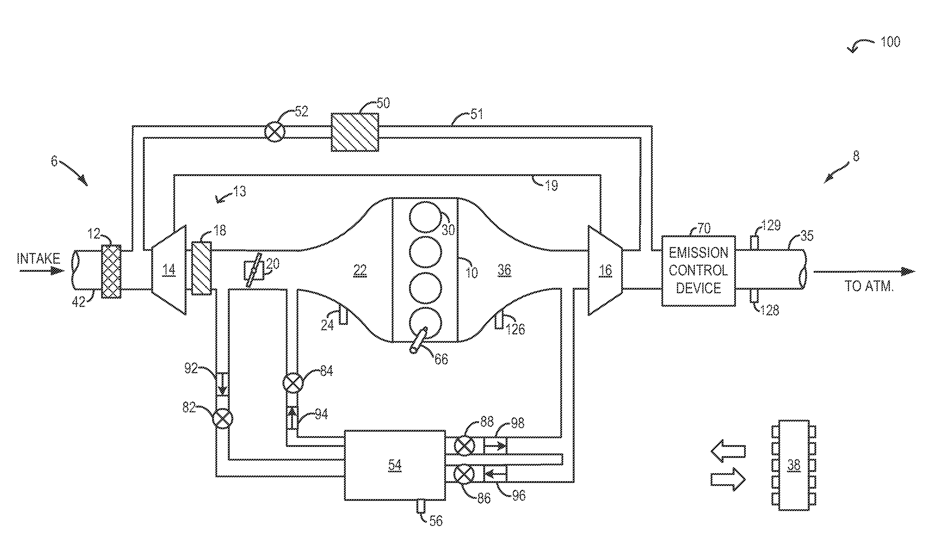
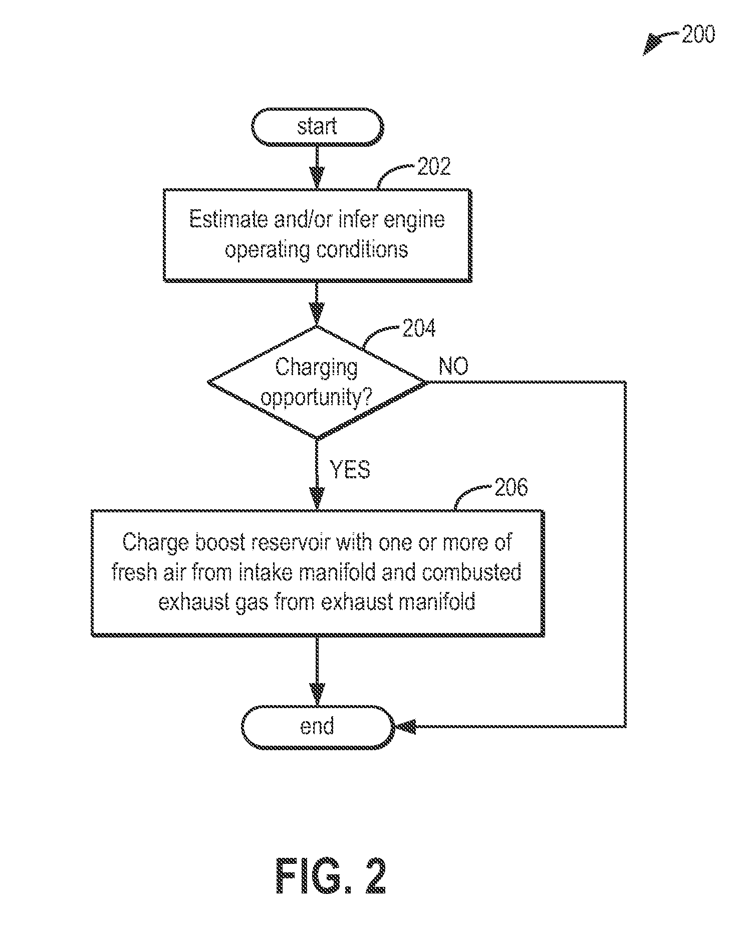
[0014]The following description relates to systems and methods for reducing turbo lag in a boosted engine including a boost air reservoir, such as in the engine system of FIG. 1. By discharging pressurized charge from the boost reservoir to the intake manifold or exhaust manifold in response to a tip-in, exhaust gas temperatures and pressures can be quickly raised, and a boosting device turbine can be rapidly spun-up. An engine controller may be configured to perform a control routine, such as the example method of FIG. 2, to charge the boost air reservoir with one or more of combusted exhaust gas from the exhaust manifold or fresh intake air from the intake manifold, when charging opportunities are available. The controller may be further configured to perform a control routine, such as the example method of FIG. 3, to discharge the pressurized charge from the reservoir into the intake manifold and / or the exhaust manifold based on engine operating conditions as well as the composit...


PUM


Abstract

Methods and systems are provided for reducing turbo lag in a boosted engine. A boost reservoir coupled to the engine may be charged with compressed intake air and / or combusted exhaust gas. The pressurized charge may then be discharged during a tip-in to either the intake or the exhaust manifold.

Description

TECHNICAL FIELD[0001]This application relates to the field of motor-vehicle engineering, and more particularly, to air induction in motor vehicle engine systems.BACKGROUND AND SUMMARY[0002]A boosted engine may offer greater fuel efficiency and lower emissions than a naturally aspirated engine of similar power. During transient conditions, however, the power, fuel efficiency, and emissions-control performance of a boosted engine may suffer. Such transient conditions may include rapidly increasing or decreasing engine load, engine speed, or mass air flow. For example, when the engine load increases rapidly, a turbocharger compressor may require increased torque to deliver an increased air flow. Such torque may not be available, however, if the turbine that drives the compressor is not fully spun up. As a result, an undesirable power lag may occur before the intake air flow builds to the required level.[0003]It has been recognized previously that a turbocharged engine system may be ada...

Claims


Application Information

Patent Timeline
Patent Type & Authority Patents(United States)
IPC IPC(8): F02B33/44F02D41/00F02D23/02F02B37/14F02B37/00F02D21/08F02D41/10
CPCF02B37/00F02B37/14F02D21/08F02D23/02F02D41/0007F02D41/10F02M26/05F02M26/06F02M26/10F02D41/0047F02D2200/602Y02T10/144Y02T10/12
Inventor ROLLINGER, JOHN ERICFULTON, BRIEN LLOYDGATES, FREEMAN CARTERRICHARDS, ADAM J.
Owner FORD GLOBAL TECH LLC
Why Eureka
Try Eureka