Optimal design method for furnace pressure control of regenerative industrial heating furnace

A furnace pressure control and optimization design technology, which is applied to furnace control devices, lighting and heating equipment, furnaces, etc. Frequent movements and other problems, to achieve the effect of improving combustion control effect, reducing hardware investment, and reducing maintenance costs

Active Publication Date: 2019-01-04
XIAMEN UNIV TAN KAH KEE COLLEGE
View PDF8 Cites 0 Cited by
  • Summary
  • Abstract
  • Description
  • Claims
  • Application Information

AI Technical Summary

Problems solved by technology

[0004] However, since the flue damper is located on the furnace loading side, it is relatively far from the furnace pressure detection point on the furnace discharge side, and the furnace has a large space, so there is a problem of lag in control; and because of the influence of the production rhythm, the discharge and furnace loading The time interval of the billet is unstable, so that the opening and closing of the furnace door has a large and irregular influence on the fluctuation of the furnace pressure of the heating furnace. Frequent actions, flue rams with frequent actions will aggravate the influence of furnace pressure fluctuations. Therefore, the closed-loop control of furnace pressure implemented only by using the furnace pressure detection signal is very unsatisfactory.

Method used


Image

  • Optimal design method for furnace pressure control of regenerative industrial heating furnace
  • Optimal design method for furnace pressure control of regenerative industrial heating furnace

Examples


Embodiment Construction

[0027] The present invention will be further described below in conjunction with the accompanying drawings and embodiments.

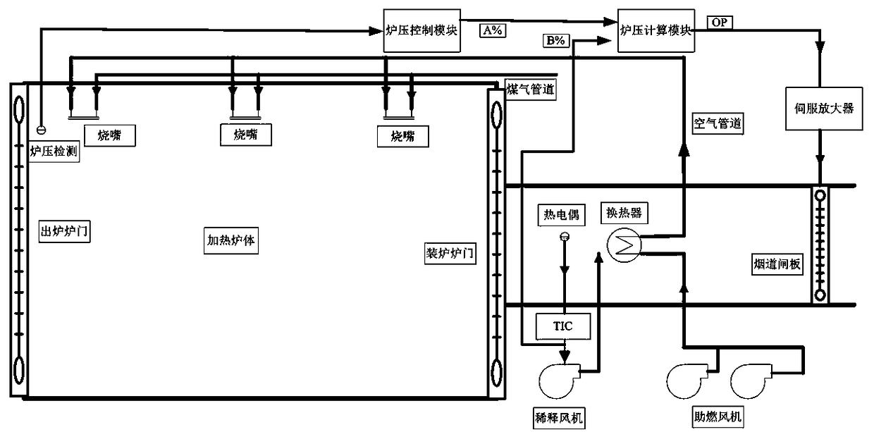
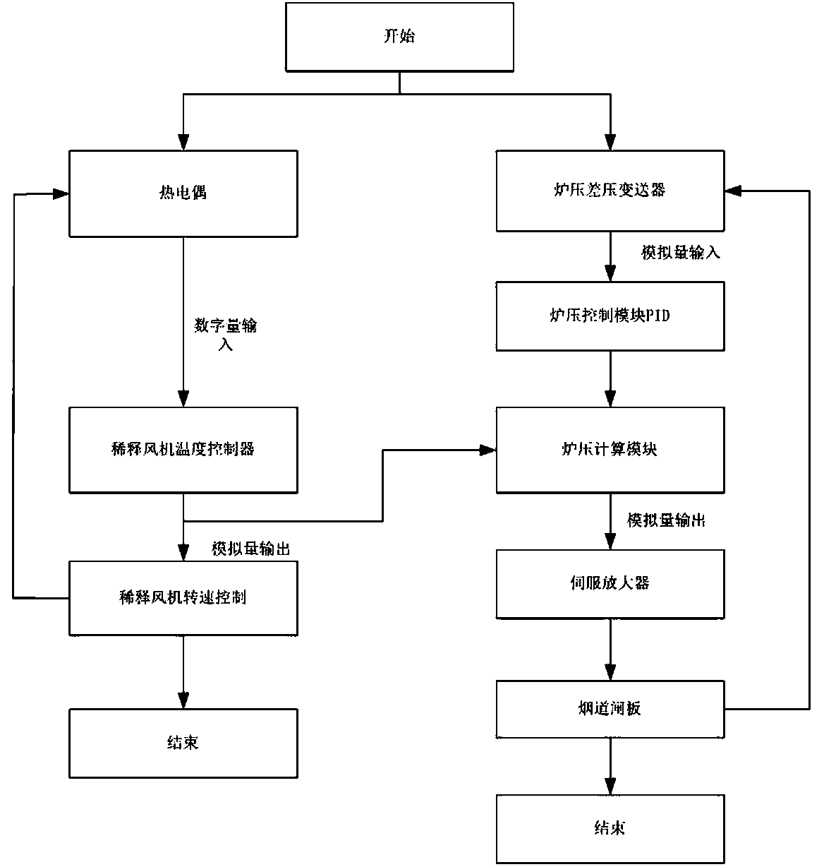
[0028] In this embodiment, the main purpose is to find an optimized furnace pressure control method, which can keep the furnace pressure stable within a certain range under the frequent opening and closing of the furnace door and the disturbance of interference signals. The specific method is to fully analyze the interference factors that cause furnace pressure fluctuations in the furnace pressure control, find out the main interference factors, and implement control on the main interference factors, so as to eliminate the interference signals that cause furnace pressure fluctuations in the bud. , at the same time reduce the proportion of the furnace pressure fluctuation signal in the control, so that the flue gate action signal not only takes into account the fluctuation of the furnace pressure detection signal, but also takes into account the fluctuati...


PUM


Abstract

The invention relates to an optimal design method for furnace pressure control of a regenerative industrial heating furnace. The regenerative industrial heating furnace comprises a furnace pressure detection device, a heating furnace body, a burner, a furnace pressure control module, a furnace pressure calculating module, a gas pipeline, an air pipeline, a servo amplifier, a heat exchanger, a thermocouple, a flue damper, a dilution fan temperature controller, a dilution fan and a combustion fan. The optimal design method comprises the steps: firstly, detecting a furnace pressure signal by a furnace pressure and differential pressure transmitter, and sending the furnace pressure signal into the furnace pressure control module; outputting a control signal according to a PID regulation rule,then sending the control signal and an output signal of the dilution fan temperature controller into the furnace pressure calculating module; adjusting a furnace pressure signal and the weighting coefficient of the rotating speed of the dilution fan, and thus obtaining different OP values; converting the OP values into a 4-20mA electrical signal by an output module of the controller to be sent tothe servo amplifier; and finally controlling the opening degree of the flue damper through the servo amplifier, and therefore completing the purpose that the flue damper is dynamically adjusted according to the furnace pressure signal and the rotating speed signal of the dilution fan.

Description

technical field [0001] The invention relates to the field of automatic control of industrial heating furnaces, in particular to an optimal design method for furnace pressure control of regenerative industrial heating furnaces. Background technique [0002] The regenerative industrial heating furnace is a heating furnace commonly used in the metallurgical industry. Generally, the mixed gas of high temperature and coke oven is used as fuel, and air is input in a certain proportion, and the combustion is completed in the heating furnace, and the heat generated is used to heat the billet in the furnace. Large heating equipment. The goal of heating furnace control is to meet the process requirements in the furnace temperature. Around this control goal, the heating furnace combustion control, furnace pressure control, total air pressure control, gas pressure control and interlocking control and other subsystems together constitute a multi-component system. parameters, strong inte...

Claims


Application Information

Patent Timeline
Patent Type & Authority Applications(China)
IPC IPC(8): F27D19/00
CPCF27D19/00F27D2019/0009F27D2019/0068
Inventor 陈文仪
Owner XIAMEN UNIV TAN KAH KEE COLLEGE
Why Eureka
Try Eureka