Operation of a gas turbine

a gas turbine and combustor technology, applied in the direction of machines/engines, mechanical equipment, lighting and heating apparatus, etc., can solve the problems of varying fuel feed rate, disadvantageous affecting power output, etc., to improve combustion control, widen the operating window of the combustor, and improve the effect of combustion control

Active Publication Date: 2015-10-27
ANSALDO ENERGIA SWITZERLAND AG
View PDF21 Cites 2 Cited by
  • Summary
  • Abstract
  • Description
  • Claims
  • Application Information

AI Technical Summary

Benefits of technology

[0013]The control method comprises the step of measurement of a variable of the second combustor and characterized by the step of varying the inert gas to air mixture in response to variations in the variable so as to at least partially compensate for the operational effects of the variable on the operation of the second combustor so as to widen the operating window of the combustor.
[0014]In one aspect the gas veils at least one of the fuels as it exits the lance as veiling providing improved combustion control and greater ability to influence self-ignition and flame stability as compared to dilution of the total second combustor feed gas by direct injection into the bulk flow.
[0015]In another aspect the variable is the composition of at least one fuel and therefore provides a means to increase the range of fuels and / or fuel compositions as well as fuel rate that can be used to operate the second combustor. In order to provide timely control and reaction to variations the fuel composition is measure by an online analyser and the mixture of inert gas and air is varied by an automated control loop taking the analyser output as a control input.
[0017]In another aspect the inert gas is steam and in a further aspect the NOx concentration in process gas from the second combustor wherein further the steam to air mixture is varied by an automated control loop based on the NOx concentration. In this way another control method for controlling NOx is provided. In yet a further aspect the variable is pulsation in process gas from the second combustor wherein further said steam to air mixture is varied by an automated control loop based on pulsation. NOx analysers can be unreliable and so providing an alternative means to controlling NOx based on the relationship that NOx concentration increases with pulsation provides increase reliability. In this way it is possible to operating closer to pulsation limits without exceeding NOx targets.

Problems solved by technology

To overcome the problem of fuel variation fuel composition limits are imposed on the second combustor, limiting operational flexibility and / or, as taught in U.S. Pat. No. 7,216,486, varying of the fuel feed rate, disadvantageously affecting power output.
As discussed in U.S. Pat No.5,617,718 a method of controlling temperature includes varying fuel rate once again disadvantageously affecting power output.
As described in U.S. Pat. No. 5,689,948 it is beneficial to add steam of the process however during the start-up process steam from the generator is not available reducing plant efficiency.

Method used


Image

  • Operation of a gas turbine
  • Operation of a gas turbine

Examples


Embodiment Construction

[0024]Preferred embodiments of the present invention are now described with reference to the drawings, wherein like reference numerals are used to refer to like elements throughout. In the following description, for purposes of explanation, numerous specific details are set forth in order to provide a thorough understanding of the invention. It may be evident, however, that the invention may be practiced without these specific details. In other instances, well-known structures and devices are shown in block diagram form in order to facilitate description of the invention.

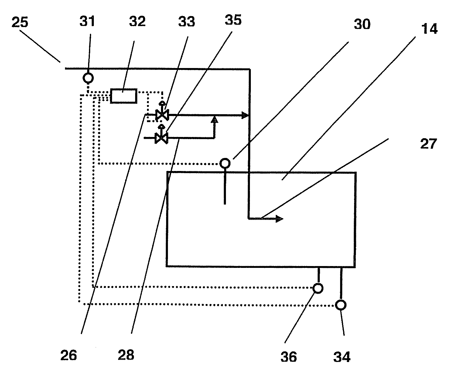
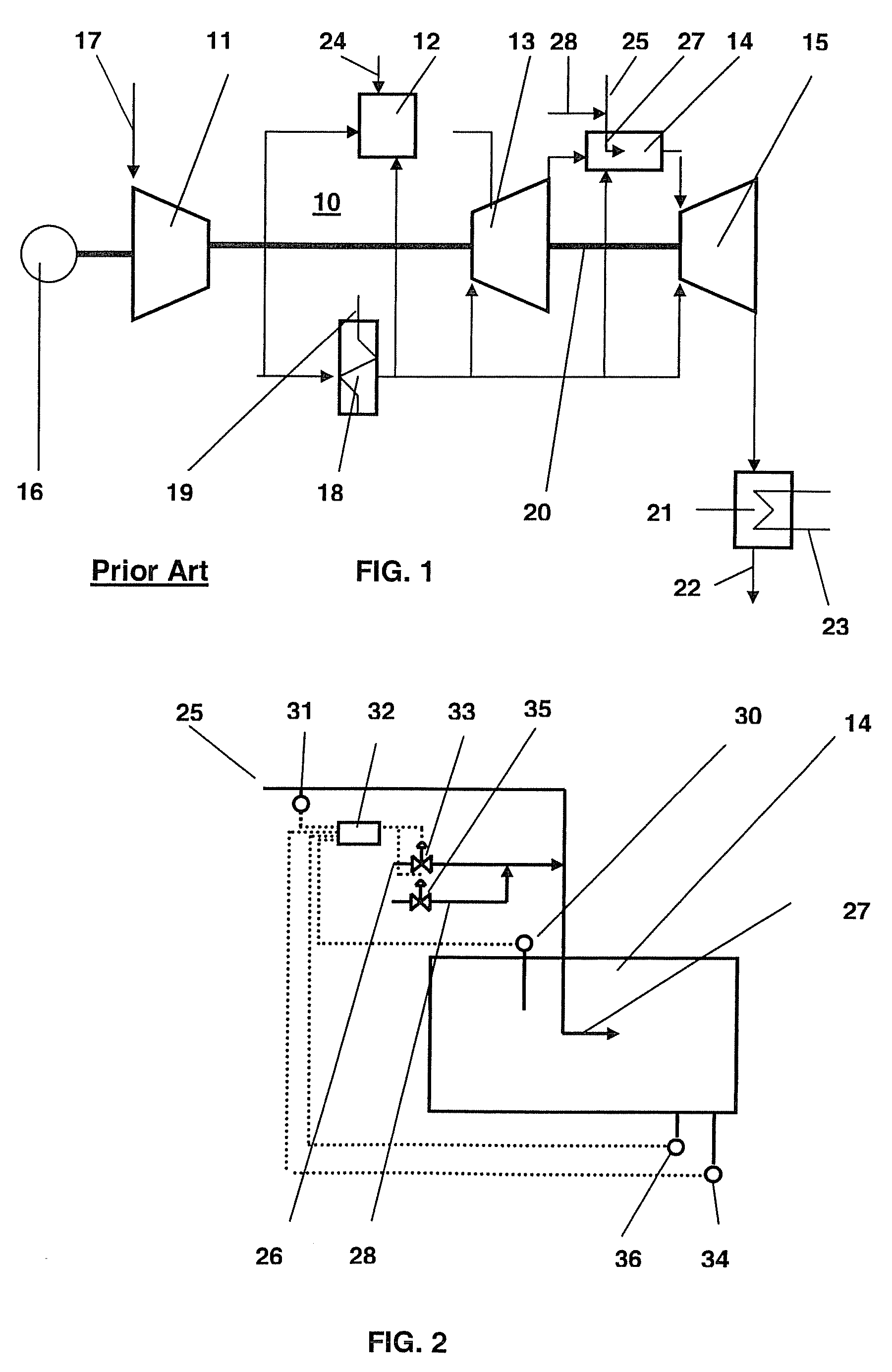
[0025]FIG. 2 shows details of a second combustor 14 of a gas turbine plant 10 of the type described in EP 0 620 362 and shown in FIG. 1. The second combustor 14 typically compromises a combustor chamber with a fuel lance 27 of the type known in the art for injecting fuel 25 together with a support air 28 for carrying or veiling the fuel. The support air 28 typically comprises air although other gases are also typica...


PUM


Abstract

Provided is a control method for a gas turbine plant having a first and a second combustors in series, such that combustion gases produced in the first combustor flows into the second combustor. The second combustor having a fuel lance with internal partitions, for injecting at least one fuel and a gas having a mixture of inert gas and support air into the second combustor. The partitions enable the gas to carry, and / or veil, at least one of the fuels as the fuel exits the lance. A variable of the second combustor is measured and the inert gas to support air mixture varies in response to variations of the variable so as to at least partially compensate for the operational effects of the variable on the operation of the second combustor.

Description

FIELD OF THE INVENTION[0001]The invention relates to control of a gas turbine plant. More particularly the invention relates the operation of a second self-ignition type combustor of a two-combustor gas turbine plant.STATE OF THE ART[0002]A gas turbine plant of the type described in EP 0620 362 is shown in FIG. 1. The plant comprises a compressor 11 for compressing combustion air for use in a first high pressure combusting chamber 12 fitted with conventional burners and for support air for the fuel injection lance of a series second combustor 14. The partially combusted air passes through a high pressure turbine 13 before flowing furthering into a second combusting chamber 14 where combustion occurs as by self ignition means. In this chamber fuel 23 is added to unburnt air from the first combustor 12 via a lance The hot gases pass through a lower pressure turbine 15 before passing through a heat recovery steam generator 21 The compressor, 11 turbines 2,13 and a generator 16 for gene...

Claims


Application Information

Patent Timeline
Patent Type & Authority Patents(United States)
IPC IPC(8): F02C9/00F02C7/228F02C6/00F23R3/34F02C9/28F23N5/00F23C6/04F23L7/00
CPCF23R3/34F02C6/003F02C7/228F02C9/28F23C6/04F23L7/00F23N5/00F23L2900/07002F23L2900/07009F23N2021/10F23N2025/08F23N2041/20F23N2221/10F23N2225/08F23N2241/20
Inventor GUETHE, FELIXHURTER, JONASCATALDI, GIOVANNIOOMENS, GIJSBERTUSWIRSUM, MANFREDJOOS, FRANZ
Owner ANSALDO ENERGIA SWITZERLAND AG
Why Eureka
Try Eureka