Vehicle power assist by brake, shock, solar, and wind energy recovery

a technology of solar energy recovery and brakes, applied in the field of energy converters, can solve the problems of performance improvement, shock deceleration energy is not completely recoverable,

Inactive Publication Date: 2008-07-15
KAUFMAN JAY STEPHEN
View PDF7 Cites 53 Cited by
  • Summary
  • Abstract
  • Description
  • Claims
  • Application Information

AI Technical Summary

Benefits of technology

[0016]It is still another object of the present invention to provide systems for efficient consumption of recovered energy.
[0017]It is yet another object of the present invention to provide a prime mover capable of burning renewable fuel with improved emissions.
[0019]Combined recovery of vehicle energy sources including kinetic (deceleration and shock), wind resistance, and solar radiation to compress atmospheric air provides substantial vehicle power assist. Recovery is by compression of atmospheric air for consumption as working fluid in vehicle prime movers. Liquefied air is imported to the vehicle as a form of energy storage by providing pre-compression cooling of prime mover working fluid. In addition, a liquefier makes supplementary liquefied air using excess recovered energy, such as during high speed driving when vehicle wind resistance, a function of the third power of speed, predominates. Excess liquefied air is transferred from the vehicle for use in other vehicles or at stationary sites. The recoverable portion of energy dissipated by a vehicle, estimated in accordance with standard highway driving cycle US-06, is: deceleration, 25%; wind resistance, 10%; shock, 10%. In addition 91 kg (200 lb) of imported liquefied air effectively increases the recovered total by 25% and clear day solar radiation adds another 8%. Energy recovery by diverse means enhances performance over a wide range of driving conditions, providing a three-fold increase in prime mover efficiency, because prime mover compression by recovered energy is a virtual energy loss. Accordingly, advantages of the present invention are illustrated as follows:
[0021](b) Another feature of the energy system in accordance with the present invention lies in providing energy recovery shock absorbers with cryogenic cooling for efficient compression of atmospheric air.
[0026](g) Another feature of the energy system in accordance with the present invention lies in providing a compact and efficient gas turbine prime mover. Compression work, using recovered vehicle energy above approximately 25% turbine load, is a virtual energy loss. Pre-compression cooling of working fluid with liquefied air enables reduced turbine inlet and exhaust temperatures. Heat input is from a renewable fuel, such as methanol. Efficiency is relatively constant over the load range and low fuel consumption lowers emissions while
[0027](h) Another feature of the energy system in accordance with the present invention lies in providing a quasi-isothermal liquefied air expander for urban driving. Compression work, using recovered vehicle energy, is a virtual energy loss.

Problems solved by technology

Recovery of only the deceleration component of kinetic energy, coordinated with electrical transfer between batteries and generators, is used in lightweight hybrid vehicles to provide limited performance improvement.
(a) U.S. Pat. No. 1,671,033 to Kimura (1928) describes a transmission with an electric generator and battery storage for recovery of vehicle deceleration, the component of vehicle kinetic energy in the direction of travel. The recovered energy, normally dissipated by engine compression and vehicle braking, is stored in batteries and used for limited electrical power assist. Deceleration energy is not completely recoverable due in part to insufficient battery capacity.
(b) U.S. Pat. No. 3,688,859 to Hudspeth and Lunsford (1972) describes compressors connected between the frame and axles of a vehicle for recovery of shock, the upward component of vehicle kinetic energy. The recovered energy, normally dissipated by shock absorbers, is used for limited pneumatic power assist. Shock energy is not completely recoverable due to compression heating.
(c) U.S. Pat. No. 6,138,781 to Hakala (2000) describes an electric generator for recovery of vehicle wind energy. The recovered energy, normally dissipated by vehicle drag force, is used for limited electrical power assist. Potential wind energy recovery is not realized because air from a wind recovery device is discharged to relatively high wake pressure. In addition, aerodynamic vehicle shapes are often used to reduce drag loss at the expense of vehicle function, such as carrying capacity.
(d) U.S. Pat. No. 5,725,062 to Fronek (1998) describes the use of a solar photo-voltaic panel atop a vehicle for recovery of solar energy radiating to a vehicle. The recovered energy, normally dissipated to the atmosphere, is used for limited electrical power assist. Solar radiation to a vehicle is not completely recoverable due in part to insufficient battery capacity.
(e) U.S. Pat. No. 4,182,960 to Reuyl (1980) describes transfer of electrical energy between vehicles and stationary sites. Solar energy recovered at a site is stored in batteries to provide power to the site and a portion is transferred to, and stored in batteries in a hybrid gas turbine-electric vehicle. The gas turbine can provide power to the site via an electric generator to supplement site solar energy. Battery storage problems include space and weight limitation, trade-off between battery life and energy discharged, replacement handling, charge time, and ventilation.
Liquefied gas transfer problems include boil-off and fill and drain connection.
Other problems include high compression work, high turbine blade and exhaust gas temperature, and expensive heat exchangers.
Operation is characterized by falling efficiency with load and compression braking is unavailable.
Low grade fuels such as kerosene can be burned, however emissions are high due to high fuel consumption and formation of compounds at high temperature.
Cryogenic expanders have low specific expansion energy due to heat input at ambient temperature.
Expanders have limited usefulness in lightweight, short range, low speed vehicles for zero emission urban use.
Combustion engine efficiency is low, and deceleration is not completely recoverable due in part to insufficient battery capacity.

Method used


Image

  • Vehicle power assist by brake, shock, solar, and wind energy recovery
  • Vehicle power assist by brake, shock, solar, and wind energy recovery
  • Vehicle power assist by brake, shock, solar, and wind energy recovery

Examples


Embodiment Construction

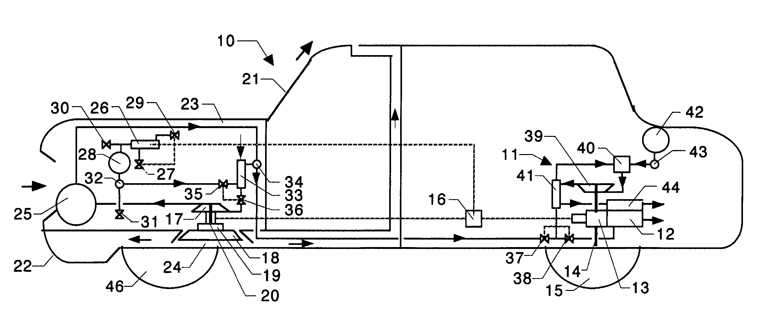
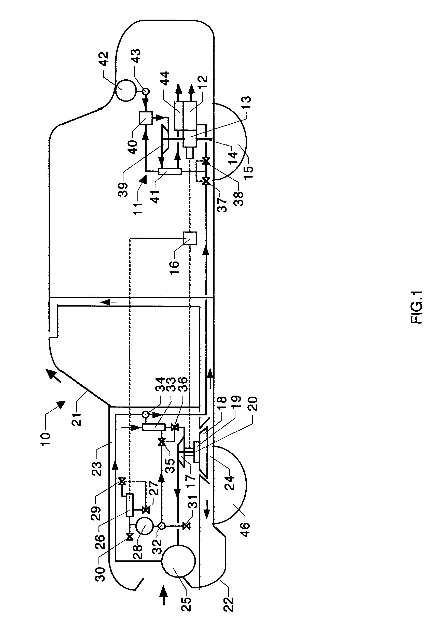
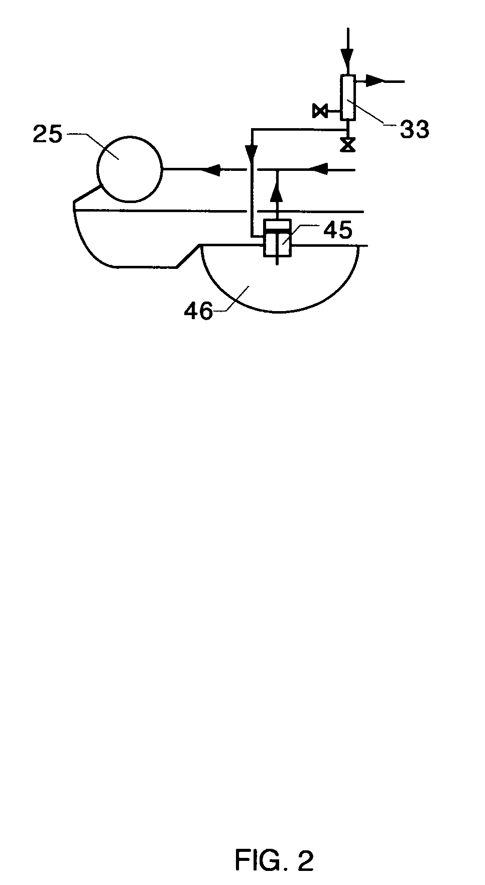
[0035]FIG. 1 illustrates a preferred embodiment of the energy recovery, storage, transfer and consumption system of the present invention installed in a motor vehicle 10. An engine 11 combined with an air expander 12 by a transmission-generator drive 13 provides prime mover propulsion to the vehicle via a shaft 14 and a rear wheel-axle assembly 15. Deceleration energy is recovered by drive 13, which is electrically connected to a motor controller 16 to power a motor-compressor 17. Wind energy is recovered by an axial wind drive 18 connected to motor-compressor 17 through a clutch 19, which provides torque to a motor-compressor shaft 20 when wind energy is sufficient. Drive 18 operates on the difference between impact pressure and wake suction pressure behind a windshield 21 and an air dam 22. Impact air pressurizes a compartment 23 and discharges through an air duct 24. Motor-compressor 17 compresses air into a compressed air tank 25. An air liquefier 26 draws atmospheric air throug...


PUM


Abstract

An energy conversion apparatus and method using recovered energy sources including motor vehicle kinetic energy (deceleration and shock) and wind resistance, supplemented by liquefied air transferred to the vehicle and by solar radiation thereto. The energy sources are combined, as available, to drive a compressor for supplying intake working fluid of a motor vehicle prime mover, wherein liquefied air provides pre-compression cooling of an atmospheric air portion of the working fluid. The liquefied air is made by recovered energy, stored and transferred between vehicles and between vehicles and stationary sites. In a hybrid version of the vehicle, exhaust heat from a combustion engine part of the prime mover increases working fluid temperature in a gas expander part, thereof; the engine and expander operating independently or together for improved vehicle propulsion efficiency.

Description

CROSS REFERENCE TO RELATED APPLICATIONS[0001]This application claims priority of Provisional Application Ser. No. 60 / 571,640, filed May 17, 2004.BACKGROUND OF THE INVENTION[0002]This invention presents an energy converter to recover and combine diverse motor vehicle energy sources for supplying compressed working fluid to a motor vehicle prime mover, wherein a liquefied air portion of the working fluid provides pre-compression cooling of an atmospheric air portion thereof; the liquefied air being made by recovered energy, stored and transferred between vehicles and between vehicles and stationary sites.[0003]Increased fuel mileage and range in conjunction with low grade fuels has long been a goal of automotive design, to make driving more economical, to conserve fossil fuels, and to reduce emission of combustion products. Recovery and combining of vehicle energy sources as available, including kinetic (deceleration and shock), wind resistance, and solar radiation, is not described i...

Claims


Application Information

Patent Timeline
Patent Type & Authority Patents(United States)
IPC IPC(8): B60K16/00B60K6/00F01B21/04B60K6/12B60K25/10
CPCB60K6/12B60K25/10F03D9/002B60L8/006B60L1/003B60L8/003B60L11/002B60L11/126B60K16/00Y02T10/6217B60K2016/003B60K2016/006B60W2710/06B60Y2400/15F05B2240/941Y02T10/6208Y02T10/7083Y02T10/90Y02E10/725Y02T10/7077F03D9/25Y02E10/728B60L50/90B60L50/62F03D9/17F03D9/32F03D9/28H02S10/12F03D9/007Y02E10/50Y02E10/72Y02E60/16Y02T10/62Y02T10/7072Y02T10/70Y02E70/30
Inventor KAUFMAN, JAY STEPHEN
Owner KAUFMAN JAY STEPHEN
Why Eureka
Try Eureka