Power control system and electric device
a power control system and electric device technology, applied in process and machine control, secondary cell servicing/maintenance, instruments, etc., can solve the problems of inevitably wasting and discarding relevant surplus power, and achieve the effect of efficient consumption of surplus power
- Summary
- Abstract
- Description
- Claims
- Application Information
AI Technical Summary
Benefits of technology
Problems solved by technology
Method used
Image
Examples
first embodiment
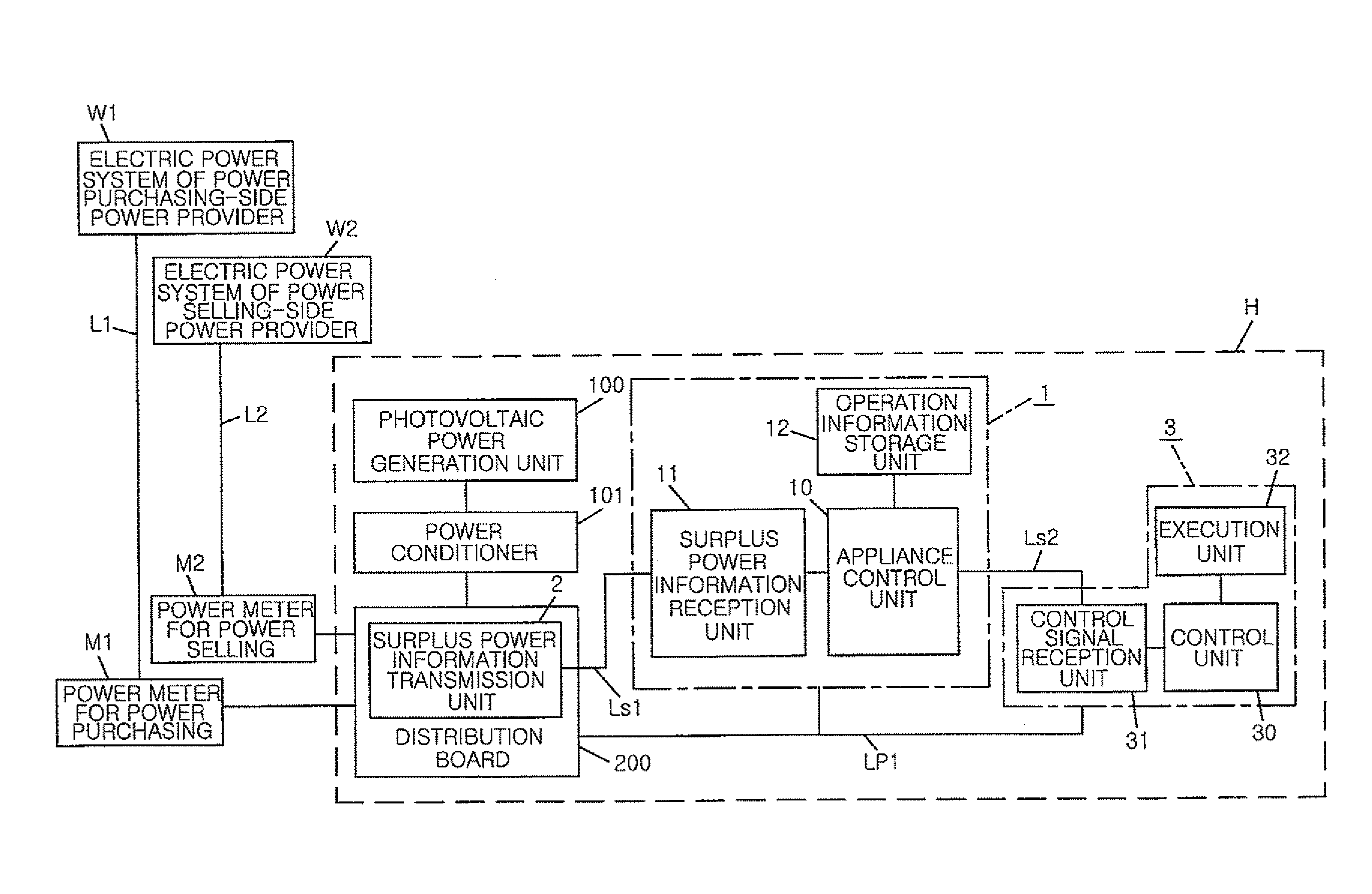
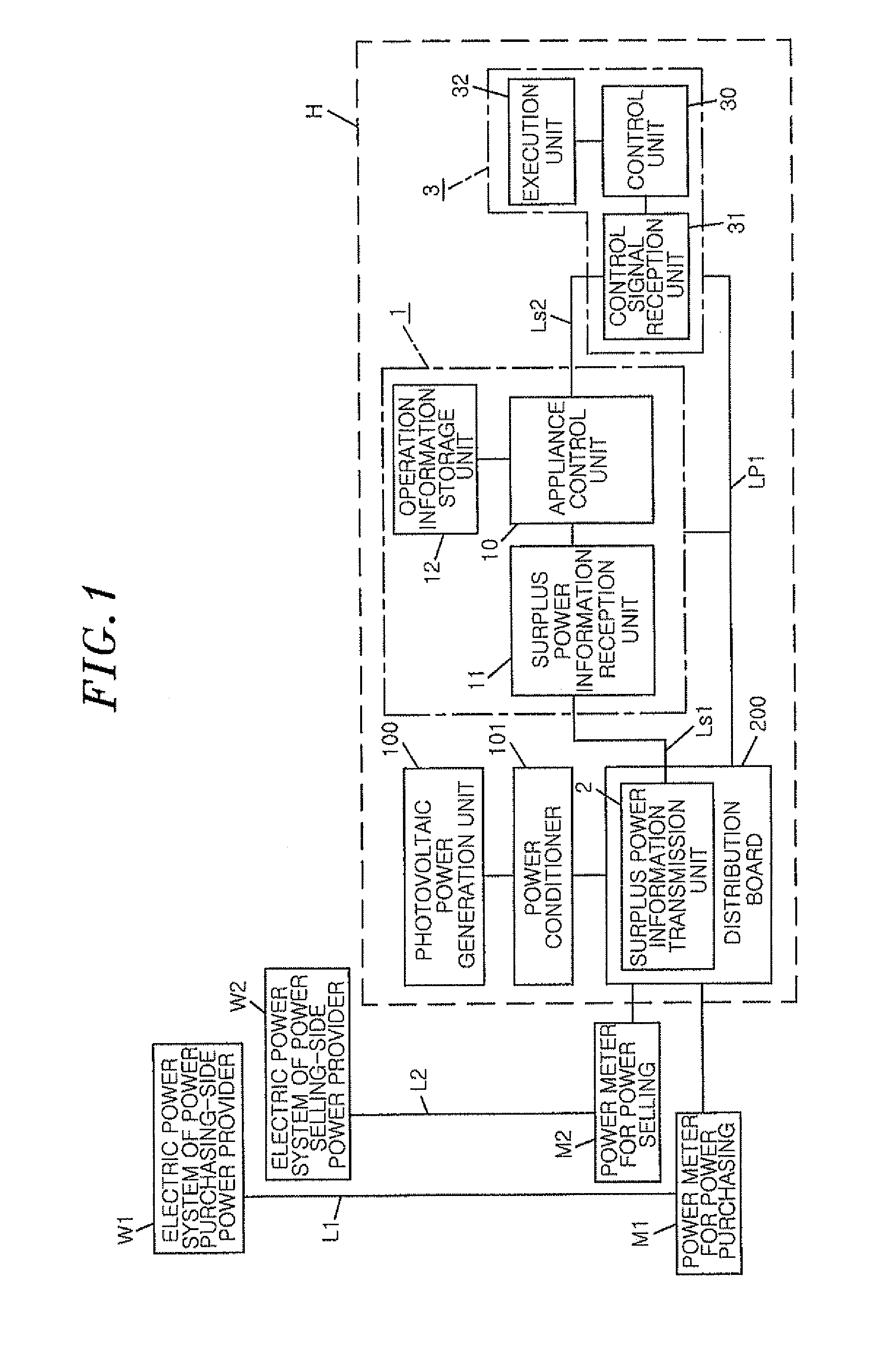
[0028]A system configuration diagram of a power control system in accordance with a first embodiment of the present invention is shown in FIG. 1. The power control system includes an appliance control device 1 and a surplus power information transmission unit 2. The power control system in accordance with the present embodiment is provided in a house H into which a power line L1 and a power line L2 are respectively led through a power meter M1 for power purchasing and a power meter M2 for power selling. The power line L1 is connected to an electric power system W1 of a purchasing-side power provider and the power line L2 is connected to an electric power system W2 of a power selling-side power provider.
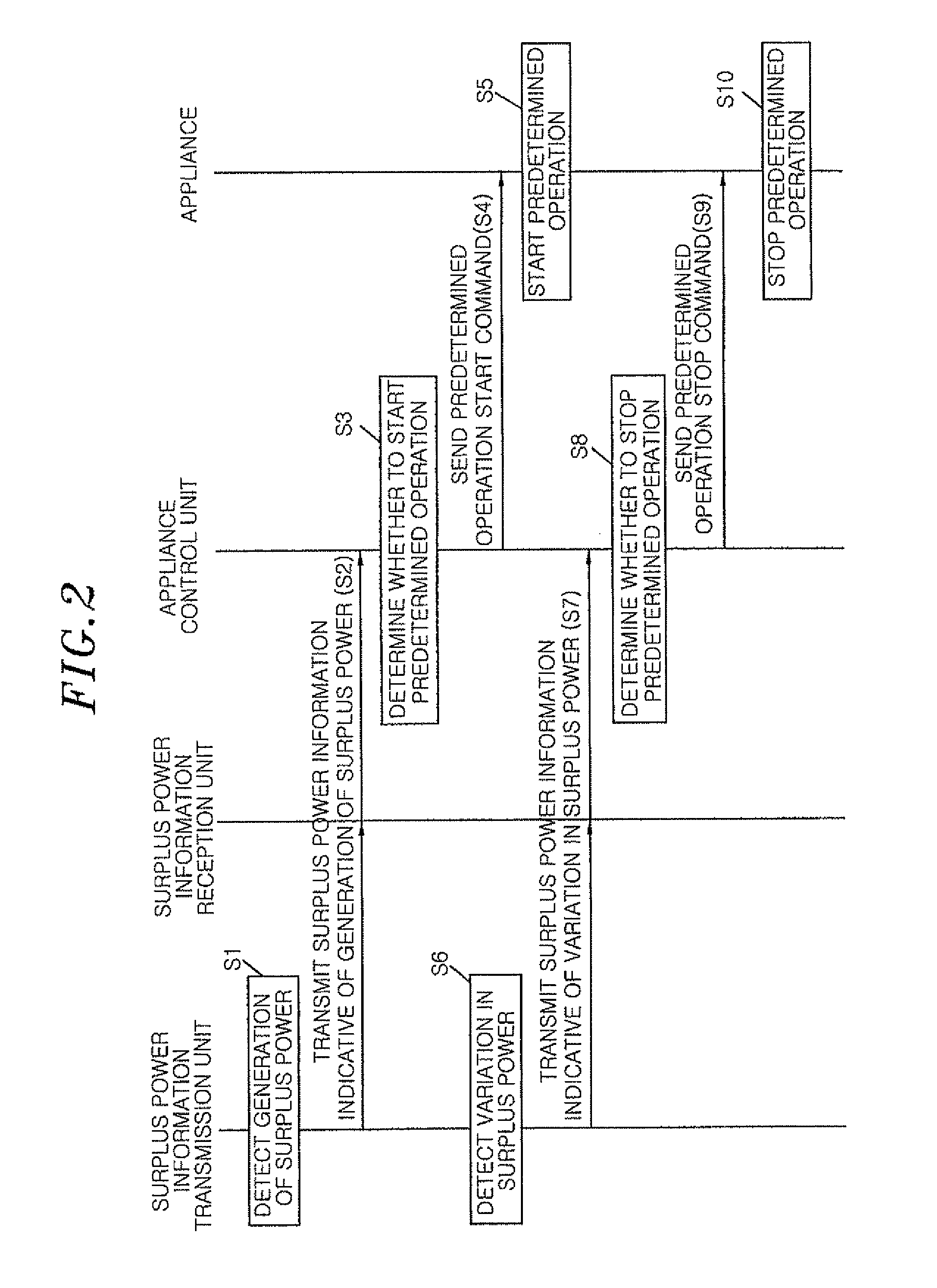
[0029]A power (AC power) supplied from the electric power system W1 of the power-purchasing side power provider via the power meter M1 for power purchasing is branched and distributed to a distribution board 200 installed in the house H and is fed to an electric device (hereinafter re...
second embodiment
[0052]A power control system in accordance with a second embodiment of the present invention is characterized in that a device consuming the surplus power is a chargeable appliance 3′ having a secondary cell (e.g., a nickel metal hydride battery, a lithium-ion battery or the like) as a power source, and in that an appliance control device 1 controls charging of the secondary cell provided in the chargeable appliance 3′. However, since the basic configuration of the power control system of the present embodiment is common to that of the first embodiment, the common components will be designated by like reference symbols with no illustration or description made thereon.
[0053]As shown in FIG. 3, the appliance control device 1 in the present embodiment includes a surplus power information reception unit 11 for receiving surplus power information transmitted from a surplus power information transmission unit 2 via a transmission line Ls1, a charging operation information storage unit 12′...
third embodiment
[0060]As shown in FIG. 5, a power control system in accordance with a third embodiment of the present invention is different from the power control system in the first embodiment in that it includes a electric storage device 103 for storing a DC power (i.e., accumulating electricity) generated by a photovoltaic power generation unit 100, a DC distribution board 102 for individually distributing the DC power generated by the photovoltaic power generation unit 100 to the electric storage device 103, a DC distribution line Lp2 in a house H, and a power conditioner 101, and DC appliances 4 (41 to 43) for using (consuming) the DC power supplied (fed) via the DC distribution line Lp2. However, the same reference numerals are assigned to components common to those of the power control system in the first embodiment, and a description thereof is omitted.
[0061]Herein, the power conditioner 101 in the present embodiment includes an AC / DC converter (not shown) for converting AC power supplied ...
PUM
| Property | Measurement | Unit |
|---|---|---|
| time | aaaaa | aaaaa |
| power | aaaaa | aaaaa |
| time | aaaaa | aaaaa |
Abstract
Description
Claims
Application Information
 - R&D
- Intellectual Property
- Life Sciences
- Materials
- Tech Scout
- Unparalleled Data Quality
- Higher Quality Content
- 60% Fewer Hallucinations
Browse by: Latest US Patents, China's latest patents, Technical Efficacy Thesaurus, Application Domain, Technology Topic, Popular Technical Reports.
© 2025 PatSnap. All rights reserved.Legal|Privacy policy|Modern Slavery Act Transparency Statement|Sitemap|About US| Contact US: help@patsnap.com


