
Electrode ignition and control of electrically operated propellants

a technology of electric ignition and propellant, which is applied in the direction of machines/engines, vehicular safety arrangements, and pedestrian/occupant safety arrangements, etc., can solve the problems of affecting the ability to control the burn rate and leaving a lot of propellant unconsumed, and achieves the effect of efficient current transfer

Active Publication Date: 2018-12-04
RAYTHEON CO
View PDF17 Cites 0 Cited by
  • Summary
  • Abstract
  • Description
  • Claims
  • Application Information

AI Technical Summary

Benefits of technology

The present invention provides a system for igniting and controlling electrically operated propellants that can efficiently use up the available propellant and be increased for larger gas generation systems. A conductive coating is used between the propellant and electrodes to help transfer the current and bond them together. The system can be used as an airbag deployment system, with the electrically operated propellant containing an ionic perchlorate-based oxidizer that has a self-sustaining threshold of at least 1,000 psi. Combustion of the propellant generates pressured gas that inflates the airbag, with interruption of the electrical input being able to extinguish combustion to control the inflation.

Problems solved by technology

Otherwise, the propellant will only ignite at or near the point of maximum current density J, typically at the surface of one of the electrodes, which hinders the ability to control the burn rate and leaves a lot of propellant unconsumed.

Method used


Image

  • Electrode ignition and control of electrically operated propellants
  • Electrode ignition and control of electrically operated propellants
  • Electrode ignition and control of electrically operated propellants

Examples


Embodiment Construction

[0036]The challenge to provide electrical ignition that provides for control of the burn rate and efficient consumption of substantially all of the available propellant, and one that is scalable to combust greater propellant mass to support larger gas generation systems remains.

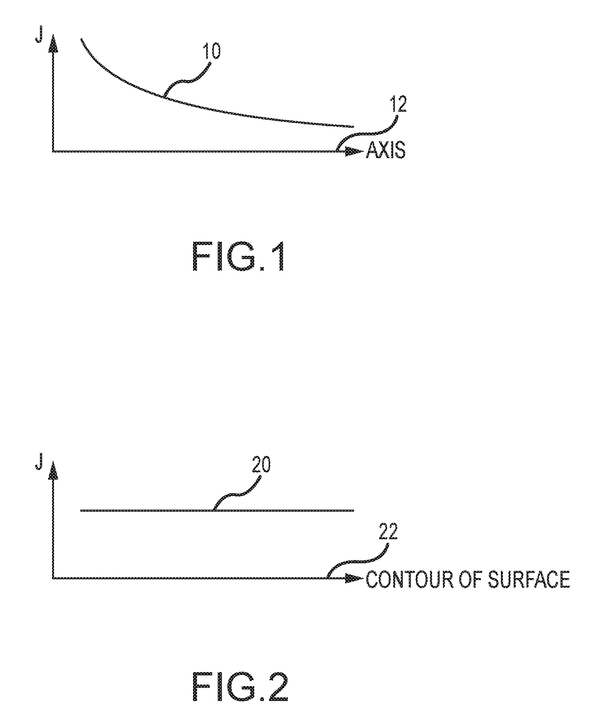
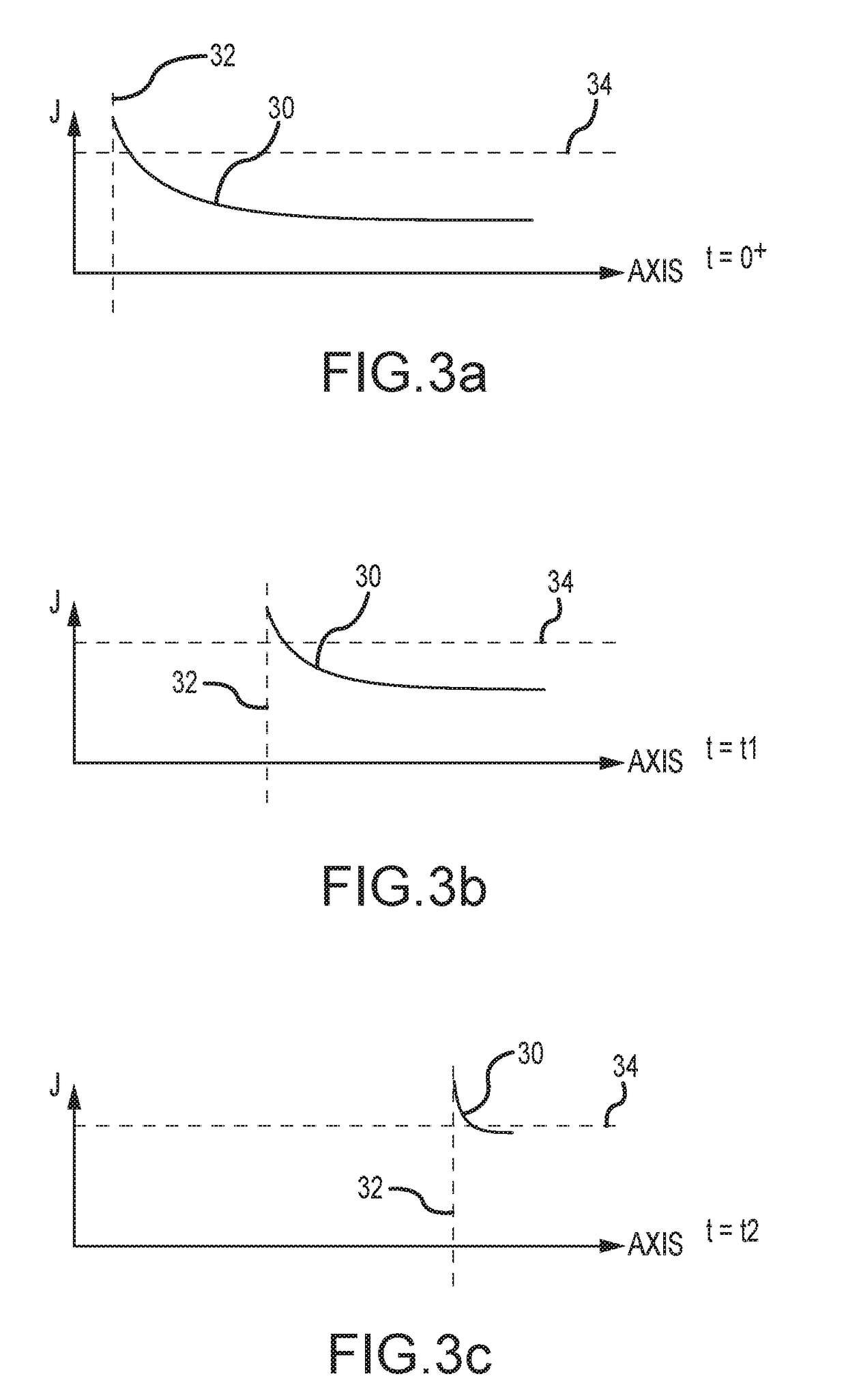
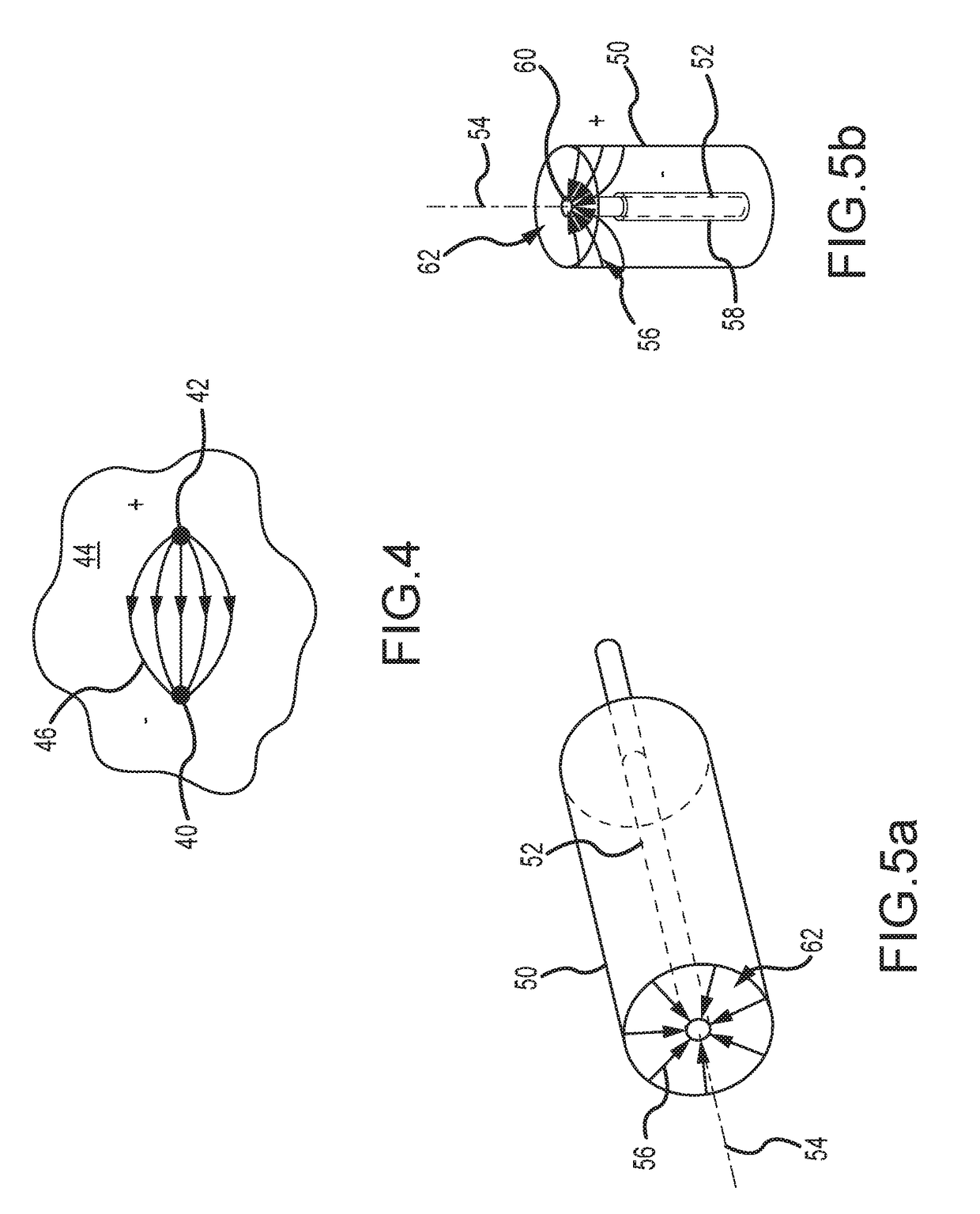
[0037]Referring now to FIGS. 1, 2 and 3a-3c, different configurations of electrode structures and electrically operable propellant in a gas generation system must provide an ignition condition at an ignition surface between a pair of electrodes that satisfies three criteria to effectively control burn rate, efficiently consume the available propellant and do so in a manner that is scalable to greater propellant mass.

[0038]First, as shown in FIG. 1, a current density J 10 along an axis 12 normal to the ignition surface exhibits a decreasing gradient. The gradient can be produced by, for example, angling and / or segmenting the electrodes and or adding a gradient concentration of a conducting / non-conducting addit...


PUM


Abstract

Electrical ignition of electrically operated propellant in a gas generation system provides an ignition condition at an ignition surface between a pair of electrodes that satisfies three criteria of a current density J that exhibits a decreasing gradient along an axis normal to an ignition surface, is substantially constant across the ignition surface and exceeds an ignition threshold at the ignition surface. These criteria may be satisfied by one or more of an angled electrode configuration, a segmented electrode configuration or an additive to the electrically operated propellant that modifies its conductivity. These configurations improve burn rate control and consumption of the available propellant and are scalable to greater propellant mass to support larger gas generation systems.

Description

BACKGROUND OF THE INVENTIONField of the Invention[0001]This invention relates to electrically operated propellants, and more particularly to controlling the ignition conditions of the propellant to efficiently and controllably ignite, burn and consume the electrically operated propellants in a manner that is scalable to combust an increased propellant mass for larger gas generation systems.Description of the Related Art[0002]All propellants are a combination of oxidizer, fuel, binder and additives. The oxidizer provides oxygen required to burn the fuel. The binder provides a structural material to bind the fuel and oxidizer. The binder itself is a fuel. Additional fuel may or may not be required. Additives may be used for a variety of purposes including to assist curing of the propellant, to control the burn rate, etc. Propellant may be used for gas generators, rocket motors, air bags and the like. It is desirable that substantially all of the propellant is or can be consumed.[0003]...

Claims


Application Information

Patent Timeline
Patent Type & Authority Patents(United States)
IPC IPC(8): F02K9/26F02K9/94F42C19/08B60R21/264F02K9/95B60R21/26
CPCF02K9/26B60R21/264F02K9/95F42C19/0819F02K9/94B60R2021/26029
Inventor SUMMERS, MATT H.VILLARREAL, JAMES K.LANGHENRY, MARK T.DANFORTH, JEREMY C.WALTER, JOHN W.
Owner RAYTHEON CO
Learn More