
Article transfer and placement apparatus

a technology for placing inserts and articles, which is applied in the directions of transportation and packaging, pile separation, packaging, etc., can solve the problems of only being able to stretch, the apparatus has the limitation of receiving and placing inserts at similar product pitches, and the assembly tends to contract and become distorted during the transfer operation, so as to reduce the amount of wrinkles

Active Publication Date: 2008-07-15
CURT G JOA
View PDF314 Cites 83 Cited by
  • Summary
  • Abstract
  • Description
  • Claims
  • Application Information

AI Technical Summary

Benefits of technology

[0006]The apparatus of the presenting invention is provided with the capability of receiving inserts at one pitch, while placing them onto a receiving conveyor at a second pitch. This allows for the placement of very short inserts onto relatively wide products, or long inserts onto relatively narrow products. This flexibility provides the user with the option of designing a wide range of product configurations in response to market demands.
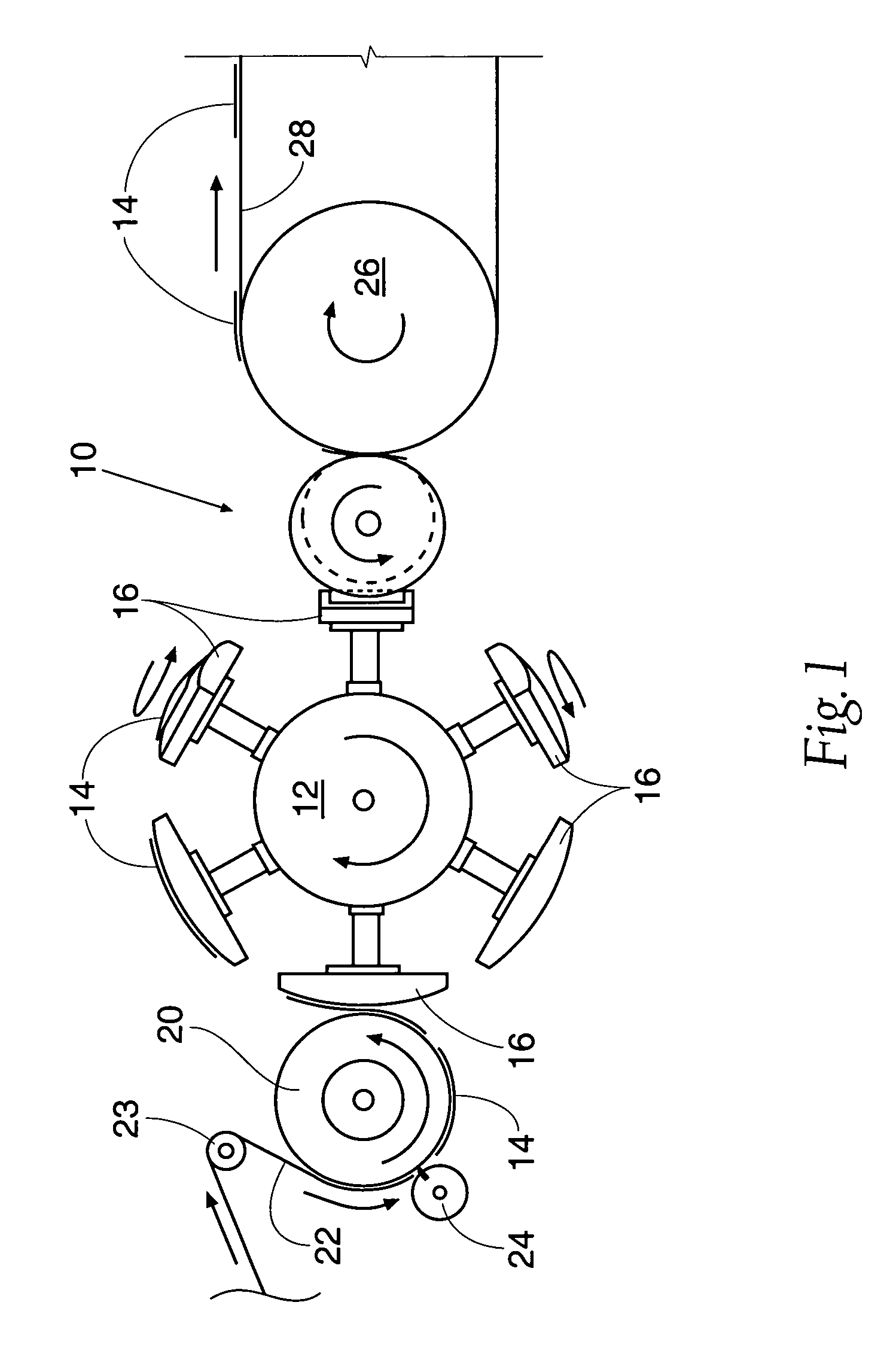
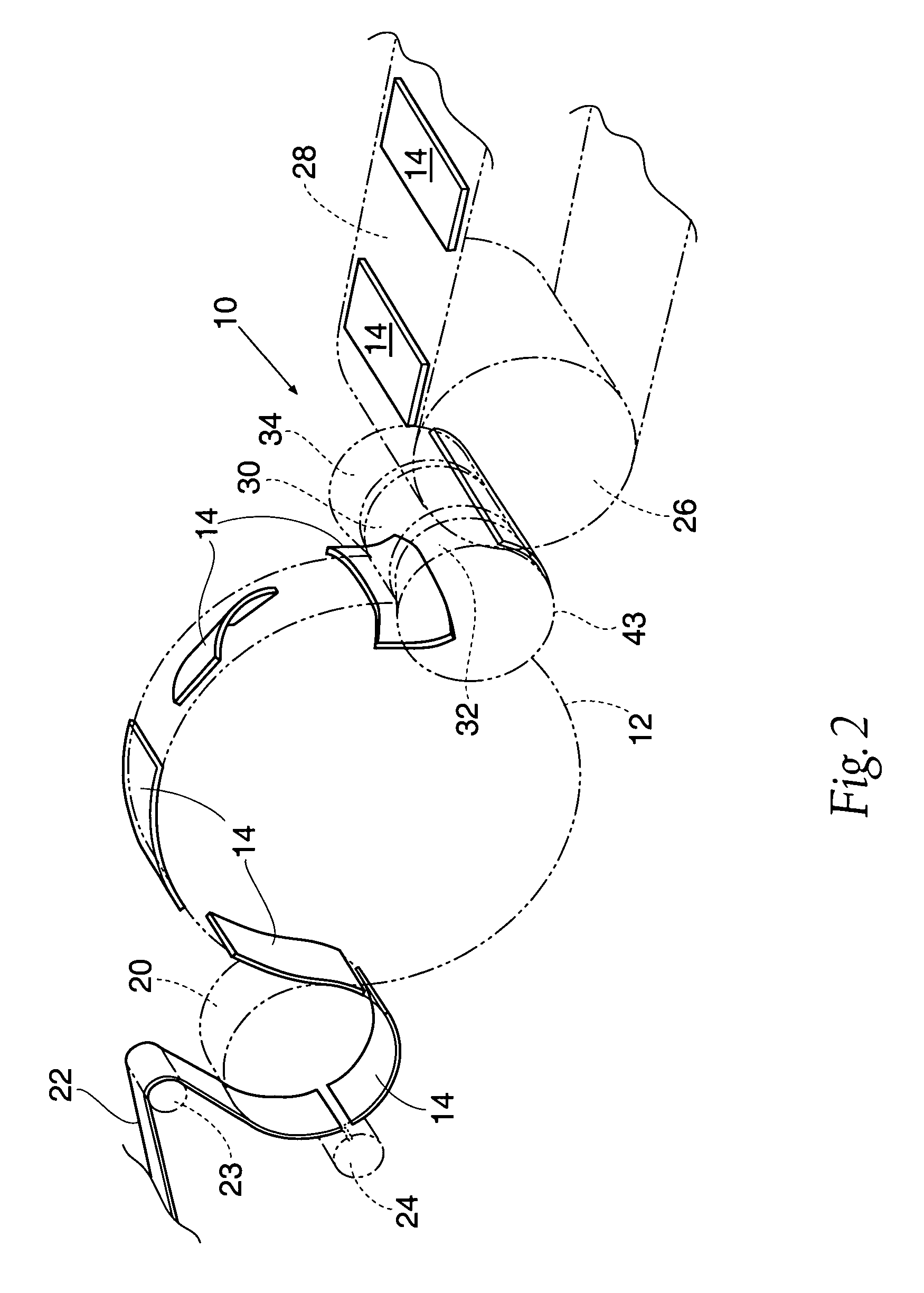
[0007]The apparatus uses servo-motor electronic cam profiling to match web velocities at the pick-up and lay-down points. An additional benefit of this new design lies in the fact that you can manipulate the exact motion profiles to optimize transfers. This is a particularly useful tool in that inserts can be manipulates to stretch them nominally in both the cross and machine directions, thereby reducing the amount of wrinkling which might occur as the stretched elastic members are handed off from one device to the next.

Problems solved by technology

Because absorbent pads are typically comprised of several webs, an absorbent core and several elastic members, there is a tendency of these assemblies to contract and become distorted during transfer operations.
However this apparatus has the limitation of receiving and placing the inserts at similar product pitches, or web velocities.
Additionally, as stated above, this apparatus is only able to stretch the inserts in a cross-direction.

Method used


Image

  • Article transfer and placement apparatus
  • Article transfer and placement apparatus
  • Article transfer and placement apparatus

Examples


Embodiment Construction

[0013]Although the disclosure hereof is detailed and exact to enable those skilled in the art to practice the invention, the physical embodiments herein disclosed merely exemplify the invention which may be embodied in other specific structures. While the preferred embodiment has been described, the details may be changed without departing from the invention, which is defined by the claims.

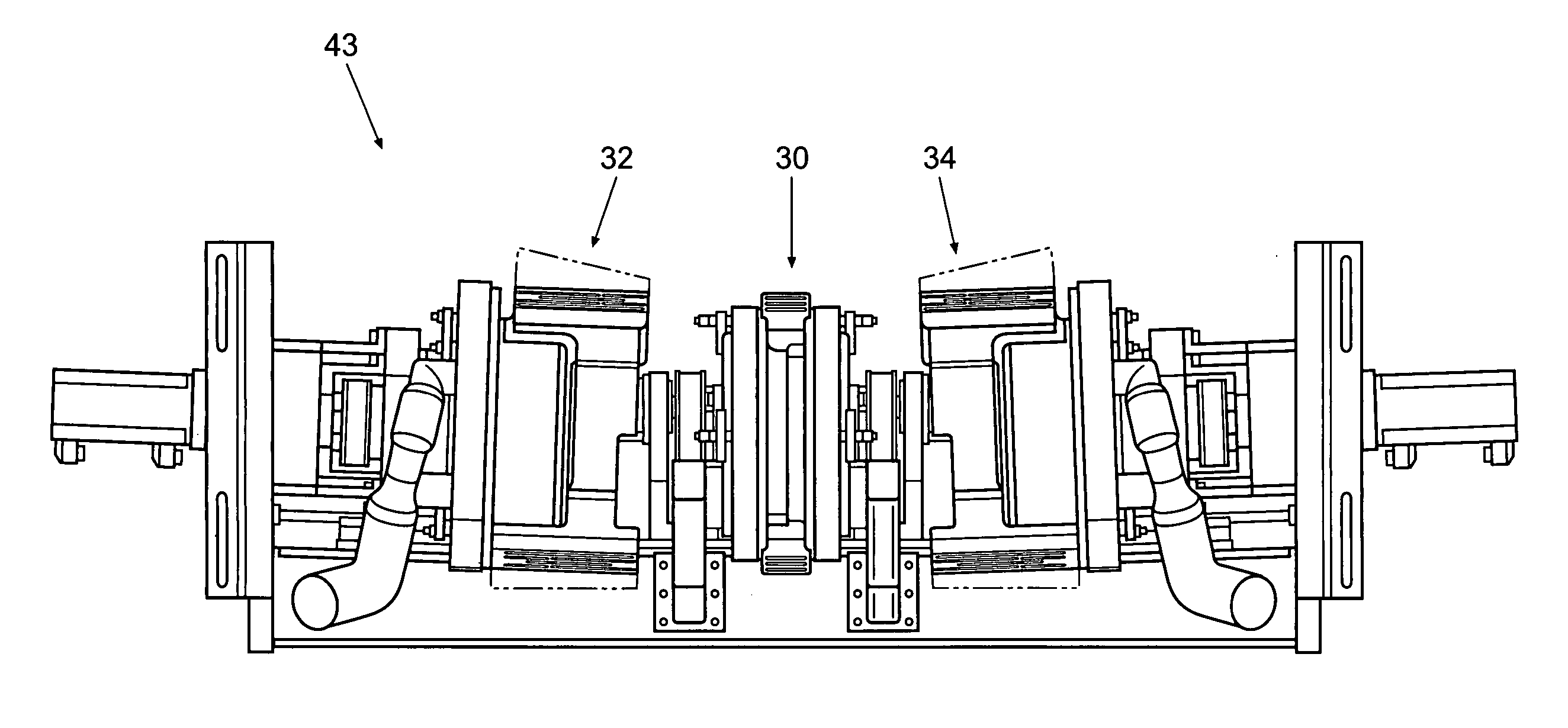
[0014]Referring more particularly to the drawings, there is seen in FIG. 1 a transfer device 10 of the present invention. The transfer device 10 is adapted to receive a series of articles from a pad turning device 12 which includes a plurality of radially extending transfer heads 16. The pad turning device 12 may be, for example, a rotary pad turner of the type more fully described in U.S. Pat. No. 5,025,910. The articles 14, such as absorbent pads, may be any elongated articles which need to be rotated 90° during the course of a manufacturing operation. Such pad turning devices 12 are especially ...


PUM

PropertyMeasurementUnit
oblique angleaaaaaaaaaa
angleaaaaaaaaaa
diameteraaaaaaaaaa

Abstract

An apparatus for transferring articles such as absorbent cores or disposable diaper chassis components from a rotary mechanism, such as a pad turner, to a linear mechanism, such as a conveyor, for further processing. The invention provides a device for picking an article from the outside of a toroidal surface, thence extending transversely under tension the article to be transferred so that at the point of deposition the article is held flat and at full length. Further, the invention allows for apparatus to match the velocity of both the first and second transfer points, even if these velocities are not the same. The device is of particular benefit where an article to be transferred is subject to internally biasing elastic forces.

Description

BACKGROUND OF THE INVENTION[0001]This invention related to an apparatus for transferring articles such as absorbent pads in the manufacture of disposable absorbent articles such as diapers, incontinence control garments or female sanitary pads as they advance along a production line.[0002]In the production and manufacture of disposable products such as sanitary napkins or pants-type diapers, it frequently becomes necessary to manufacture a component of the product in one orientation, and then to rotate that component part 90° so that it is suitably oriented for use in another step in the production process. Various devices have been developed for this purpose and are known to those experienced in the industry. Examples of such apparatus are those described in U.S. Pat. Nos. 4,726,876, 4,880,102, and 5,025,910.[0003]As discussed above, a typical article to be reoriented by the apparatus of this invention is an absorbent pad. Because absorbent pads are typically comprised of several w...

Claims


Application Information

Patent Timeline
Patent Type & Authority Patents(United States)
IPC IPC(8): B65G47/24
CPCA61F13/15764B65B9/087B65G29/00B65G47/848B65H5/12B65G47/244B65H2406/3454B65G2201/022B65H2301/33216
Inventor MCCABE, JOHN A.
Owner CURT G JOA
Learn More