Emergency lighting system with improved monitoring

a technology of emergency lighting and monitoring, applied in the direction of fire alarms, audible advertising, instruments, etc., can solve the problems of insufficient representation, insufficient monitoring, and significant labor, and achieve the effect of improving monitoring and reducing service costs

Inactive Publication Date: 2008-07-15
TYCO FIRE & SECURITY GMBH
View PDF21 Cites 38 Cited by
  • Summary
  • Abstract
  • Description
  • Claims
  • Application Information

AI Technical Summary

Benefits of technology

[0005]Integration of Emergency Lighting Individual Addressable Modules (ELIAMs) according to an embodiment of the present invention with a fire alarm system allows for better monitoring at lower service cost. Automation of the test cycle is provided. Backup of a depleted battery following the test is provided by a signaling line circuit (SLC). This enables continuous monitoring of battery condition. Required monthly testing may be eliminated. Annual test requirements can be met monthly. A system trouble condition and annunciation via the fire alarm network or other means can provide notice that a specific battery requires replacement.

Problems solved by technology

This method of battery test is inadequate to properly measure actual battery capacity.
This load represents only a 0.025 Ampere-hour (Ah) discharge, and is not really an adequate representation of battery condition, since the actual system will be required to provide 90 minutes standby.
This test requires significant labor, since a building can have many emergency lighting components.

Method used


Image

  • Emergency lighting system with improved monitoring
  • Emergency lighting system with improved monitoring
  • Emergency lighting system with improved monitoring

Examples


first embodiment

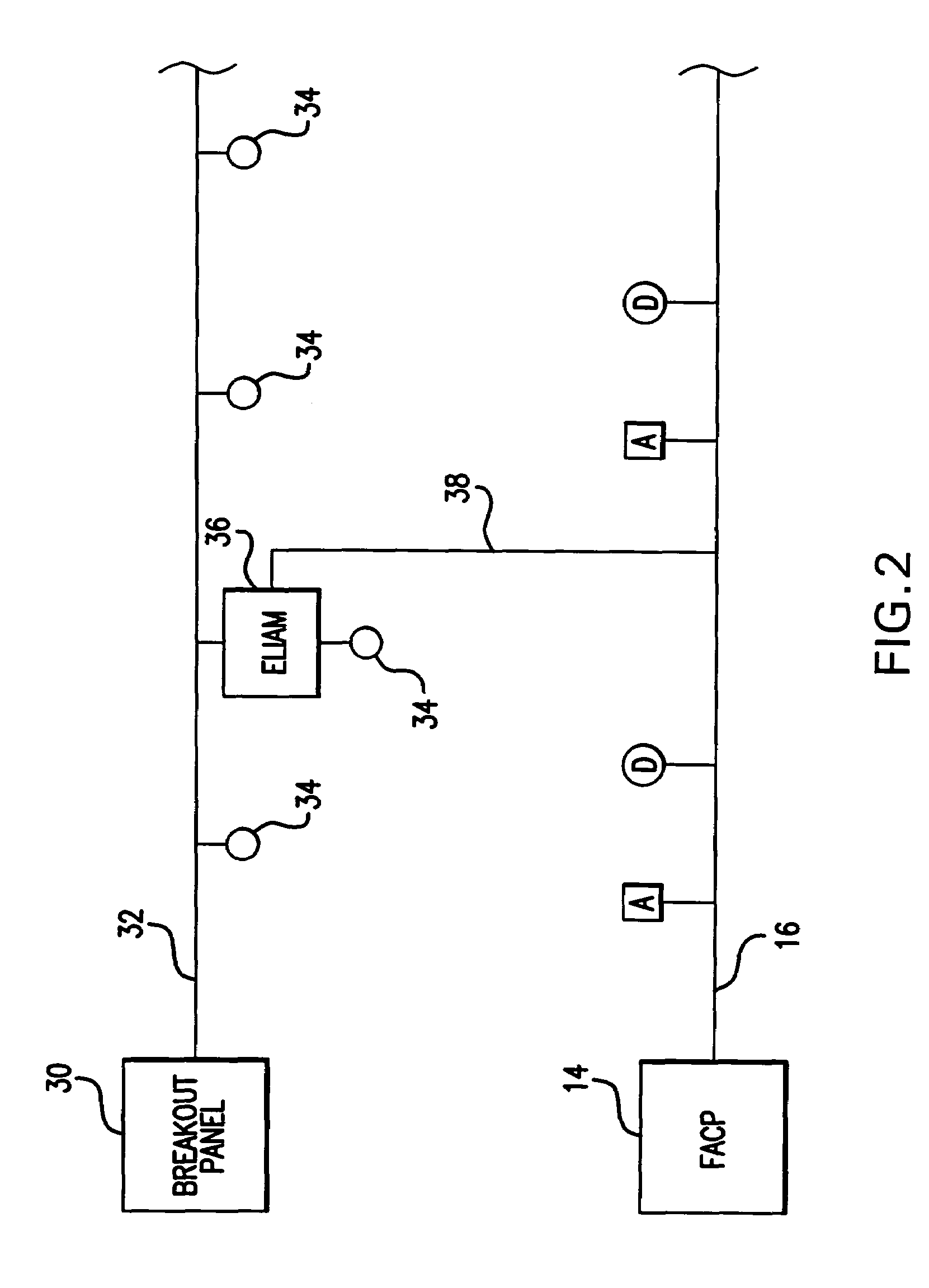
[0034]FIG. 3A is a block diagram illustrating the present invention ELIAM. Power is received through power line 32 and is normally routed to power lamp 34. In the event of an AC power loss, a controller 42 causes the lamp 34 to be powered from the backup battery 40.

[0035]A network interface 44 connects the unit to the fire alarm network 38. Upon receiving a command via the network interface 44 from the system controller 14 (FIG. 2), the ELIAM controller 42 disconnects the lamp 34 from the power line 32 and instead causes the lamp 34 to be powered from the backup battery 40.

[0036]Thus, upon a command to test the backup battery 40, the battery 40 is discharged through the lamp 34. The battery voltage or current draw may be monitored by the controller 42 and the resulting battery or lamp (no current would imply a faulty lamp) information can then be transmitted to the system controller 14.

[0037]Alternatively, rather than discharging the battery 40 through the lamp 34, the battery 40 co...


PUM


Abstract

An emergency lighting unit includes a lamp, a backup battery, and controller and a network interface. The controller connects the backup battery to the lamp upon detection of an emergency condition and loss of main power. The network interface interfaces with and receives commands via a fire alarm network. Each emergency lighting unit has a unique identifier with respect to the fire alarm network.

Description

RELATED APPLICATION(S)[0001]This application claims the benefit of U.S. Provisional Application No. 60 / 502,338, filed Sep. 12, 2003. The entire teachings of the above application(s) are incorporated herein by reference.BACKGROUND OF THE INVENTION[0002]Emergency lighting systems are dependent on battery backup to provide egress lighting when AC power has failed. Presently, emergency lighting units are provided with manual test capability. Typically, these units provide a test switch, or other manual means for initiating a test, which is held in the “ON” position for 90 seconds each month. The battery is tested by applying a load for the duration in which the switch is pressed.[0003]This method of battery test is inadequate to properly measure actual battery capacity. For example, a given unit loads the battery with 1 Ampere during the 90 second load test. This is the same as the emergency lighting load. This load represents only a 0.025 Ampere-hour (Ah) discharge, and is not really a...

Claims


Application Information

Patent Timeline
Patent Type & Authority Patents(United States)
IPC IPC(8): G09F25/00G08B5/36G08B7/06G08B17/00
CPCG08B17/00G08B7/06
Inventor BARRIEAU, MARK P.BARRIEAU, JOHNPAUL P.BROOKS, JEFFREY R.
Owner TYCO FIRE & SECURITY GMBH
Why Eureka
Try Eureka