Image processing apparatus

a technology of image processing and apparatus, applied in the field of image processing apparatus, can solve the problems of difficult orientation recognition, difficult orientation recognition, and high comparison accuracy, and achieve the effect of increasing comparison accuracy

Inactive Publication Date: 2008-07-15
FANUC LTD
View PDF21 Cites 5 Cited by
  • Summary
  • Abstract
  • Description
  • Claims
  • Application Information

AI Technical Summary

Benefits of technology

[0009]Specifically, the present invention provides an improved image processing apparatus of the type that selects an image captured in an imaging direction close to the imaging direction of a target included in an input image, from among a plurality of sample images obtained by imaging the target in a plurality of different directions. The improved image processing apparatus creates an appropriate masking image from the sample images, and masks out interfering background to a certain extent before comparing the input image with the sample images, thereby increasing the comparison accuracy. The present invention has the following three modes.

Problems solved by technology

This technique is used in many applications, but the wider the range of possible orientations of the target, the more difficult orientation recognition becomes.
If the target faces in an arbitrary three-dimensional direction in a pile of parts, for example, its orientation is very difficult to recognize.
In this target orientation recognition method, the critical issue is to maximize the accuracy of the comparison.
One of the factors lowering the comparison accuracy is a non-uniform background (non-target area) present in the input image used for recognition.
At the site where the target is actually recognized, however, the background of the obtained input image includes unpredictable clutter such as objects other than the target to be recognized.
As described above, one factor that lowers the sample image comparison accuracy is an irregular background coexisting with the target in the input image.
If the comparison is carried out under conditions in which the effect of the background is removed, the recognition accuracy should improve, but the background removal method presented in the above reference is problematic in that the intersection window is often too narrow and the recognition accuracy may actually be worsened.

Method used


Image

  • Image processing apparatus
  • Image processing apparatus
  • Image processing apparatus

Examples


first embodiment

[0035]First, FIG. 3 illustrates an image comparison processing in the A first masking image is created before the input image is compared with each sample image. The first masking image is created by assuming that pixels in an area covering the area of a target in all sample images are valid pixels while pixels in the remaining area are invalid pixels. This processing can be explained more specifically as follows:

[0036]Pixels in all sample images and the input image will be represented in common as Aij (i=1, 2, 3, . . . m; j=1, 2, 3, . . . n; the total number of pixels is m×n), and the s-th sample image will be denoted Ss (s=1, 2, 3 . . . q; q is the total number of sample images). If a pixel Aij (i=1 to m, j=1 to n) is within an appropriate pixel area in which the target appears in at least one sample image Ss (s=1 to q), the image processing apparatus 20 determines pixel Aij as a valid pixel. Otherwise, pixel Aij becomes an invalid pixel, that is, if a pixel Aij is within an area...

second embodiment

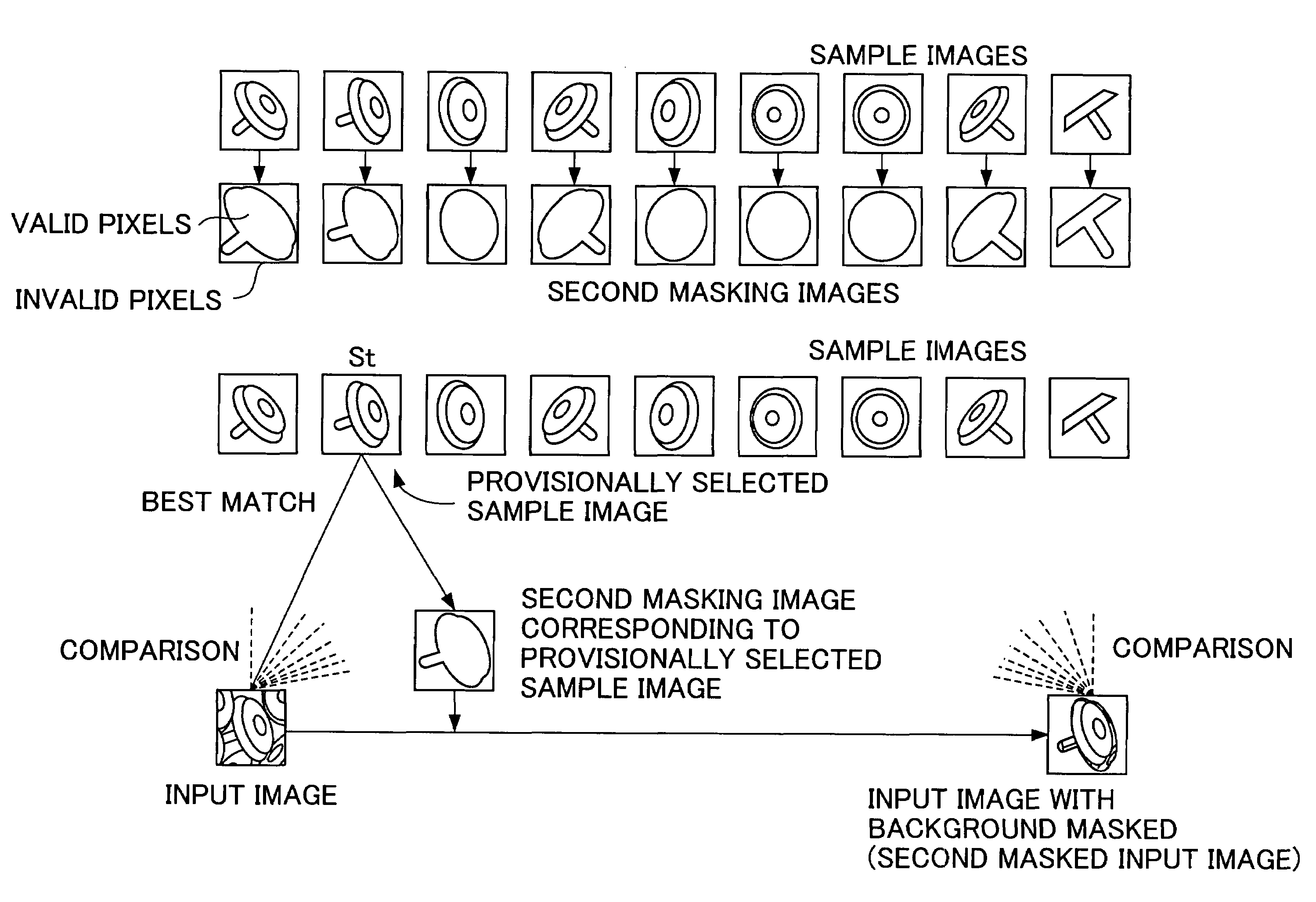
[0040]Next, FIG. 4 illustrates an image comparison process in the In this embodiment, two-stage comparisons are made between the input image and each sample image. The first stage comparison is carried out using all pixels in each image, and the sample image providing the best match with the input image is chosen as a provisionally selected sample image St.

[0041]In the second stage comparison, a second masking image created from the provisionally selected sample image St is used. The second masking image is created according to a rule slightly different from the first masking image: the second masking image is created for individual sample image. In the description below, the second masking image is created from the provisionally selected sample image St. For the provisionally selected sample image St, therefore, it is assumed that pixels in an area including the target are valid pixels and pixels in the remaining area are invalid pixels. The processing in the embodiment is describ...

third embodiment

[0044]Finally, FIG. 5 illustrates the image comparison process in the In this embodiment, first and second masking images are created before the input image is compared with each sample image. The first masking image is created, as described above, by assuming that pixels in an area covering the area of a target in all sample images are valid pixels while pixels in the remaining area are invalid pixels. Further, a second masking image is created for each sample image by assuming that pixels in the area including the area of target are valid pixels while pixels in the remaining area are invalid pixels.

[0045]Comparisons between the input image and each sample image are carried out two times. In the first comparison, pixels corresponding to the valid pixels in the first masking image are used for comparison. With this comparison, an image providing the best match with the input image is chosen from among sample images as a provisionally selected sample image Su. The second comparison ...


PUM


Abstract

A first masking image of an input image is created by assuming that pixels in an area including the area of a target in all sample images are valid pixels while pixels in the remaining area are invalid pixels. The first masking image is used in a first comparison between the input image and each sample image to select an image that provides a best match as a provisionally selected sample image. In a second comparison, a second masking image corresponding to the provisionally selected sample image is used to select a final sample image. The second masking image is created from an individual sample image by assuming that pixels in an area including the area of the target are valid pixels while pixels in the remaining area invalid pixels.

Description

BACKGROUND OF THE INVENTION[0001]1. Field of the Invention[0002]The present invention relates to an image processing apparatus used for recognizing parts and other targets by using vision sensors and, more particularly, to an image processing apparatus that uses images to recognize the positions and orientations of targets that may be oriented in various directions.[0003]2. Description of the Related Art[0004]To enable a robot or another automatic machine to handle a target object that is not positioned precisely, such as a part, the target is imaged and its position, orientation, and so on are recognized from the resulting image data. This technique is used in many applications, but the wider the range of possible orientations of the target, the more difficult orientation recognition becomes. If the target faces in an arbitrary three-dimensional direction in a pile of parts, for example, its orientation is very difficult to recognize.[0005]To address the above problem, Japanese Pat...

Claims


Application Information

Patent Timeline
Patent Type & Authority Patents(United States)
IPC IPC(8): G06K9/00G06K9/62G06T1/00G06K9/36G06K9/64G06T7/00
CPCG06K9/6203G06T7/0044G06T7/0004G06T7/74G06V10/7515G06V10/20
Inventor TAKIZAWA, KATSUTOSHIKUMIYA, HIDETOSHI
Owner FANUC LTD
Why Eureka
Try Eureka